
Power supply efficiency optimization

Active Publication Date: 2009-04-02
NOKIA TECHNOLOGLES OY
View PDF17 Cites 64 Cited by
  • Summary
  • Abstract
  • Description
  • Claims
  • Application Information

AI Technical Summary

Benefits of technology

[0006]A third embodiment of the invention is a computer program product comprising a computer readable memory medium storing a computer program configured to be executed by control apparatus of a portable electronic device, the portable electronic device having at least one processor and at least one switching mode power supply, wherein when executed the computer program product is configured to cause the portable electronic device to detect a change in processor operating mode of the at least one processor; to transmit a signal indicating the change in the processor operating mode to the switching mode power supply; to receive the signal at the switching mode power supply; and to change a power supply operating mode of the switching mode power supply in dependence on receipt of the signal indicating the change in the processor operating mode.
[0007]A fourth embodiment of the invention is a portable electronic device comprising: power supply means for supplying power to other components of the portable electronic device; for operating in at least two power supply operating modes when supplying power to the other components; for receiving operating mode signals from at least one other component of the portable electronic device; and for changing power supply operating modes in dependence on the operating mode signals received from the at least one other component; processor means fo

Problems solved by technology

However, such modes of operation have several drawbacks.
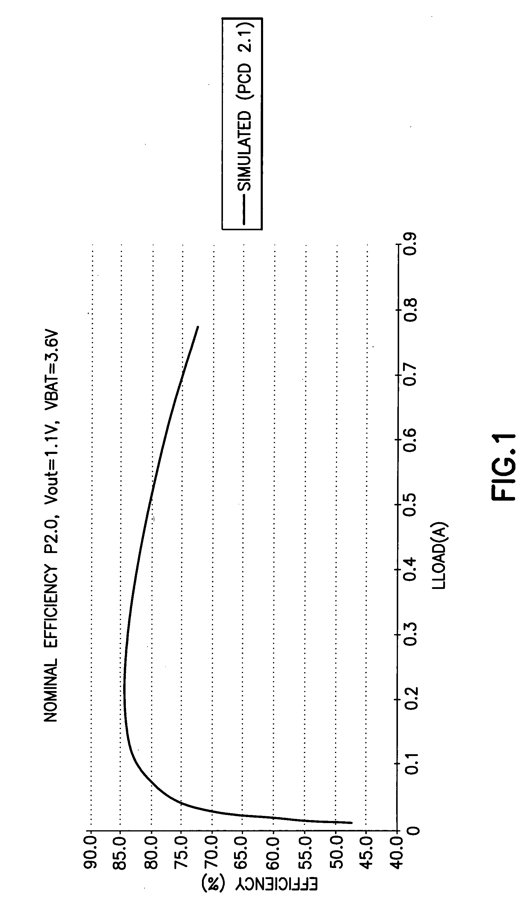
In particular, continuously maintaining the power supply in a state of readiness for operating modes that may or may not occur degrades the efficiency of the power supply and particularly the expected battery life.
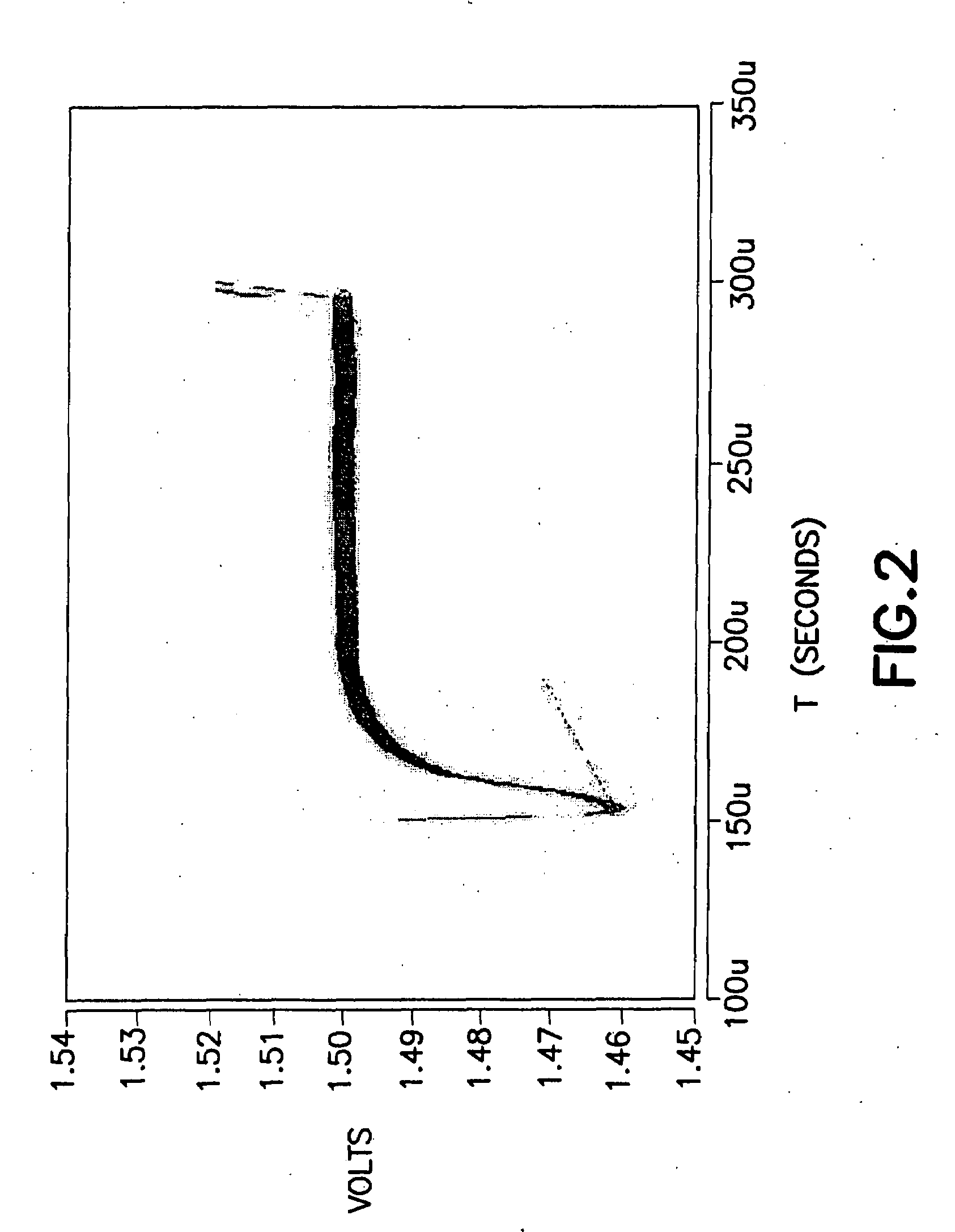
In addition, transient response is less than optimal, in particular when switching into a low power mode when the power supply is designed to expect a high power mode.

Method used


Image

  • Power supply efficiency optimization
  • Power supply efficiency optimization
  • Power supply efficiency optimization

Examples


Embodiment Construction

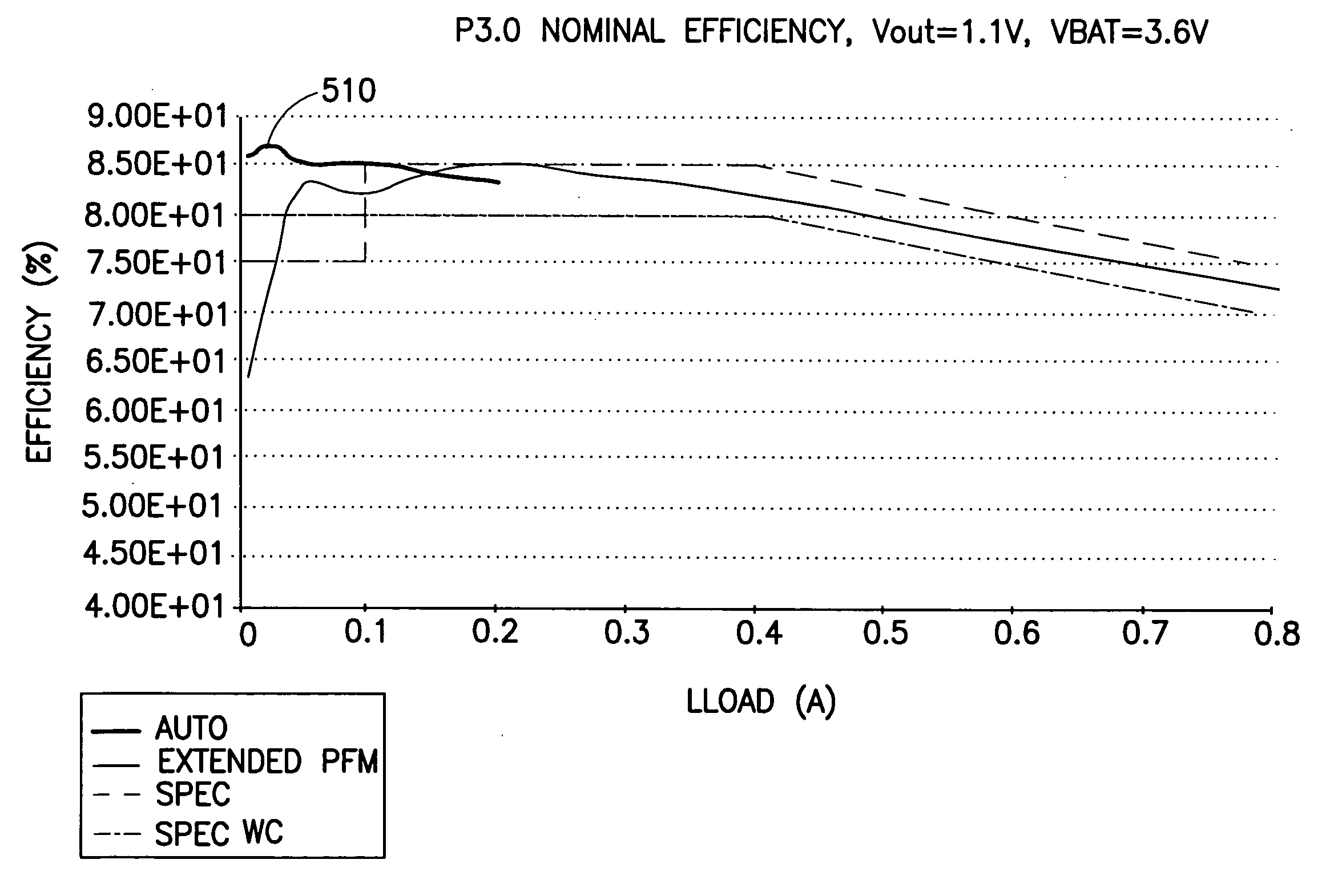
[0017]Embodiments of the invention make use of processor power saving modes that already exist to signal to the power supply in advance of the change in load so as to enable improved power supply efficiency while also achieving good load transient response. The invention communicates processor idle state information to the power supply so that the power supply can optimize its efficiency during the periods when one or more processors are waiting for an interrupt. Similarly, when the host device is completely idle (often termed deep sleep mode whereby all high frequency clocks are disabled) the power supply can be optimized for this case.

[0018]The concept of deep sleep low power supply optimization has not been extended to address active modes or load transient management. Existing solutions attempt to determine the correct mode automatically in the power supply device by sensing the load but cannot achieve as good performance as would be possible with the present invention since con...


PUM


Abstract

Methods and apparatus operative in a portable electronic device having a processor and a switching mode power supply detect entry of the processor into a power saving mode during active operations and signal the switching mode power supply that the processor has entered a power saving mode. In response to the signaling the switching mode power supply optimizes its operating state in order to increase power supply efficiency.

Description

TECHNICAL FIELD[0001]The invention generally concerns power control in battery-powered portable electronic devices and more particularly concerns signaling operating modes of processors and other power-consuming devices in portable electronic devices to power supplies so that the power supplies can select operating modes in order to improve efficiency and transient performance.BACKGROUND[0002]Many portable electronic devices (mobile phones are a good example) require high performance microprocessors / digital signal processors and hardware accelerators (HWA) to support the high data rates and high video quality. Such high performance microprocessors, digital signal processors and hardware accelerators in turn require high peak current power supplies. These power supplies are normally made from switched mode power supplies and are designed to handle the maximum currents efficiently. However these same power supplies also are required to operate very efficiently for low power audio appl...

Claims


Application Information

Patent Timeline
IPC IPC(8): G06F1/32
CPCG06F1/3203Y02B60/1221G06F1/3237Y02D10/00
Inventor NOUSIAINEN, JAAKKO
Owner NOKIA TECHNOLOGLES OY
Learn More