Balloon cuff tracheostomy tube

a tracheostomy tube and balloon cuff technology, which is applied in the field of balloon cuff tracheostomy tube, can solve the problems of large inflammation and generation of secretions from the tissues surrounding the tube, unable to fully recover, and the conventional tracheostomy tube is generally not well anchored within the body

Active Publication Date: 2009-04-09
AVENT INC
View PDF100 Cites 35 Cited by
  • Summary
  • Abstract
  • Description
  • Claims
  • Application Information

AI Technical Summary

Benefits of technology

[0011]The device further includes an inflatable balloon enveloping a portion of the tube. More particularly, the balloon has a distal balloon portion substantially centered about and attached to the distal end portion of the tube. The balloon also has a proximal balloon portion attached to the bend region of the tube and positioned substantially off-center about the bend region below the proximal plane of the device. Upon inflation, this configuration provides for expansion of the balloon around the distal end portion of the tube and the proximal end portion of the tube below the proximal plane of the device to seal the trachea below the tracheal stoma and avoid sealing the trachea above the tracheal stoma. Desirably, this configuration of the balloon will allow secretions to exit the stoma.

Problems solved by technology

ET tubes are inserted into the mouth and down the throat past the glottis, and because of this cause a great deal of inflammation and generation of secretions from the tissues surrounding the tube.
The discomfort that results from the location of the ET tube in the throat and the inflammation caused by the ET tube means that most patients are kept sedated while an ET tube is inserted.
Conventional trach tubes, unfortunately, are generally not well anchored within the body, as shown in FIG. 1.
This instability and lack of anchorage can lead to a number of problems.
Another issue caused by the poor anchoring of trach tubes in the trachea is that they may be accidentally dislocated, sometimes coming out of the airway completely.
The reintroduction of the tube can be very difficult, since the stoma may be inflamed or damaged by the removal of the original tube.
Additionally, even under normal installation conditions, the distal tip of the trach tube can cause damage and inflammation to the posterior wall of the trachea if it rubs against the tracheal wall as the patient moves, coughs, etc.
While these tracheostomy tube devices may provide suitable control over the movement of the tube, the balloons appear to seal the tracheal stoma, thus limiting access to that region.
Sealing the tracheal stoma inhibits the removal of secretions through the stoma and can result in the same problems as ET tubes vis a vis VAP.
The tracheostomy tube device may have balloon walls that are non-uniform in thickness.

Method used


Image

  • Balloon cuff tracheostomy tube
  • Balloon cuff tracheostomy tube
  • Balloon cuff tracheostomy tube

Examples


Embodiment Construction

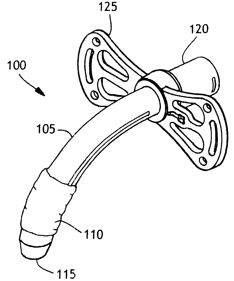
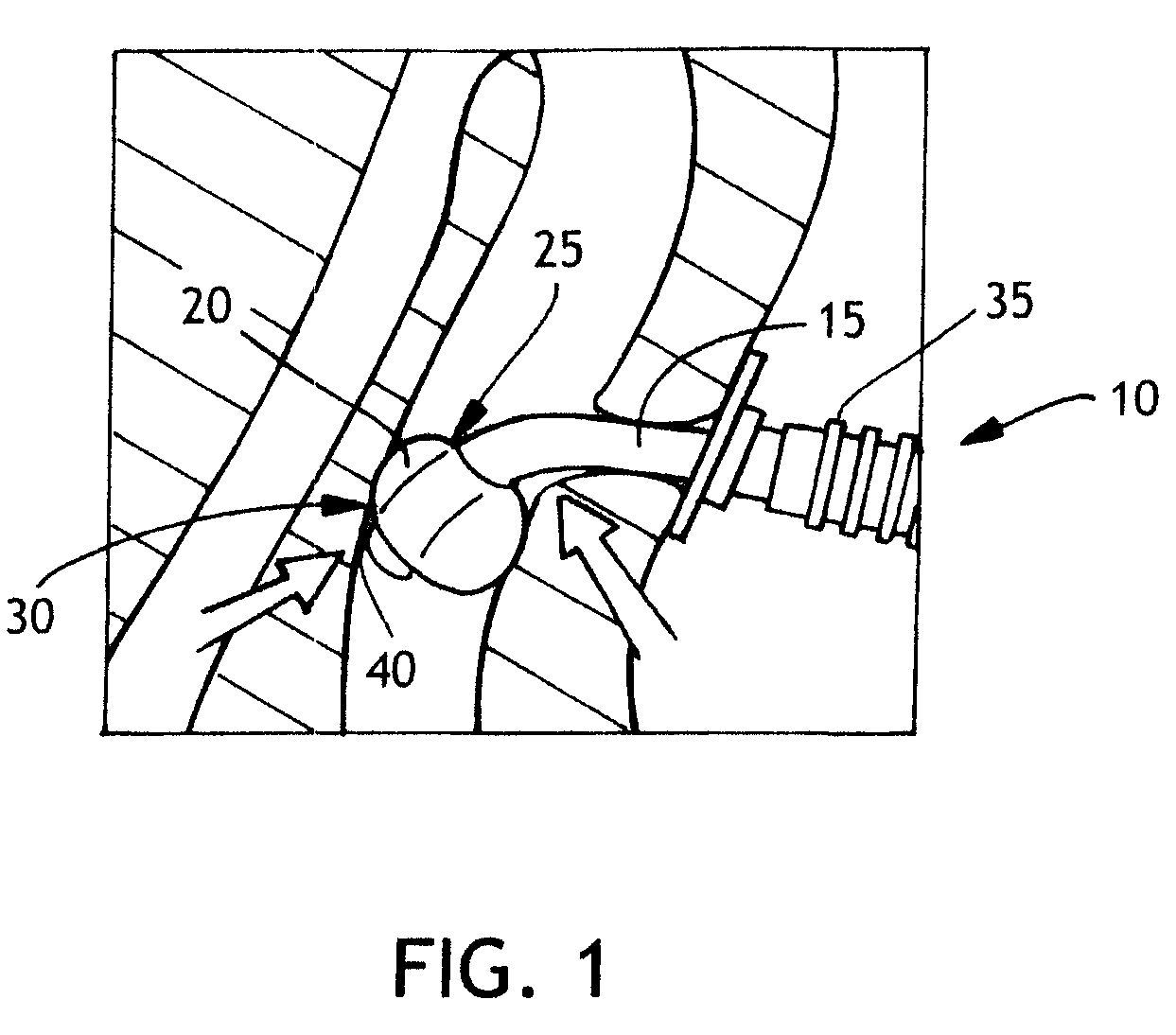
[0029]Conventional tracheostomy tubes are inserted through a stoma in the throat that has been dilated in order to receive the trach tube. Their “anchoring” or the controlled location of the tube within the trachea remains a concern with these known tubes. FIG. 1 is an illustration of such a conventional cuffed tracheostomy tube 10 composed of a tube 15 and an inflatable cuff 20. In this configuration, the cuff 20 is centered on the tube 15 at the proximal point of attachment 25 and the distal point of attachment 30 and these points of attachment located on the tube 15 are contiguous or at an angle of approximately 180 degrees.

[0030]In FIG. 1 illustration, the balloon is deformed as a result of compressive forces on the inflated balloon. These compressive forces may be caused by the weight of the ventilator tubing 35 or by movement of the patient that presses the ventilator tubing against an obstacle, or by other causes. These compressive forces may cause the distal tip 40 of the tr...


PUM


Abstract

There is provided a balloon cuffed tracheostomy tube with a balloon designed so as to enhance the tube's anchorability without sealing the tracheal stoma. The tracheostomy tube device includes a conventional curved hollow tube. The distal end of the tube is adapted for insertion through a tracheal stoma and into the tracheal lumen of a patient's throat. The device further includes an inflatable balloon enveloping a portion of the tube. The balloon has a distal portion substantially centered about and attached to the distal end portion of the tube. The balloon also has a proximal portion attached to the bend region of the tube and positioned substantially off-center relative to the proximal portion of the tube and about the bend region below the proximal plane of the device. Upon inflation, this configuration provides for expansion of the balloon around the distal end portion of the tube and the proximal end portion of the tube below the proximal plane of the device to seal the trachea below the tracheal stoma and to avoid sealing the trachea above the tracheal stoma. This configuration of the balloon should allow secretions to exit the stoma so that they do not accumulate and become a possible source of ventilator acquired pneumonia.

Description

[0001]This application claims the benefit of commonly assigned U.S. provisional application 60 / 994,664, filed Sep. 20, 2007 and having attorney docket number 64391725US01.BACKGROUND OF THE INVENTION[0002]As concerns about ventilator acquired pneumonia (VAP) continue to mount in the practice of medicine, particularly in the developed world, attention has been focused on ways to reduce the frequency and severity of this potentially fatal condition. It has been found that one source of bacterial leading to pneumonia can come from secretions from the throat of patients intubated with endotracheal tubes (ET tubes) for long periods of time. ET tubes are inserted into the mouth and down the throat past the glottis, and because of this cause a great deal of inflammation and generation of secretions from the tissues surrounding the tube. The discomfort that results from the location of the ET tube in the throat and the inflammation caused by the ET tube means that most patients are kept seda...

Claims


Application Information

Patent Timeline
Patent Type & Authority Applications(United States)
IPC IPC(8): A62B9/06
CPCA61M16/0434A61M16/0465A61M16/0479A61M16/0445A61M16/0488
Inventor CUEVAS, BRIAN J.SLEVA, MICHAELSCHUMACHER, JAMES F.KENOWSKI, MICHAEL A.CHAN, SAM C.FRANK, RYAN C.
Owner AVENT INC
Why Eureka
Try Eureka