Combustion Type Power Tool

Inactive Publication Date: 2009-04-09
HITACHI KOKI CO LTD
View PDF11 Cites 0 Cited by
  • Summary
  • Abstract
  • Description
  • Claims
  • Application Information

AI Technical Summary

Benefits of technology

[0011]It is therefore an object of the present invention is to provide a combustion type power tool capable of avoiding wasteful injection of combustible gas from the gas canister even if an unintentional operation of the push lever takes place while the gas canister remains set in the tool.
[0012]Another object of the invention is to provide a combustion type power tool capable of avoiding wasteful injection of combustible gas from the gas canister based on an unintentional operation of the push lever, and at the same time, capable of avoiding wasteful electric power consumption even if a battery used as power supply remains set in the tool.
[0014]When the prohibiting mechanism provides the prohibiting phase, the combustion chamber frame cannot be moved past the predetermined position, and therefore, the drive mechanism cannot drive the gas canister to its gas injection phase. Hence, even if the gas canister remains set in the canister housing, while the tool is not being used, gas is not wastefully consumed when the push lever is unintentionally operated as long as the prohibiting mechanism is at the prohibiting phase. This saves resources and enhances safety. Further, the operability of the tool can be increased because the gas canister need not be removed from the tool after using the tool.
[0021]The power switch can be turned on to supply electric power from the power source to the ignition control circuit and turned off to shut off the power supply. Here, no electric power is supplied to the ignition control device as long as the prohibiting mechanism remains at the prohibiting phase even if the power source such as a battery remains set in the power tool while the tool remains unused. Thus, no control current is supplied even if the push lever is unintentionally operated. This avoids wasteful consumption of power source and, ultimately, saves resources and enhances safety. In addition, troublesome work such as setting the battery before using the tool or removing the same after using the tool can be avoided. Moreover, over-discharging of the battery can be prevented, and the lifetime of the battery can therefore be prolonged.

Problems solved by technology

When the prohibiting mechanism provides the prohibiting phase, the combustion chamber frame cannot be moved past the predetermined position, and therefore, the drive mechanism cannot drive the gas canister to its gas injection phase.

Method used


Image

  • Combustion Type Power Tool
  • Combustion Type Power Tool
  • Combustion Type Power Tool

Examples


Embodiment Construction

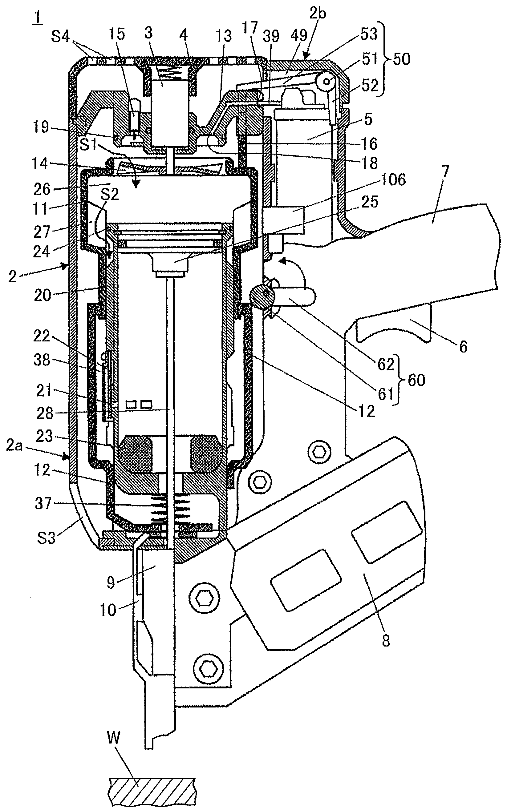
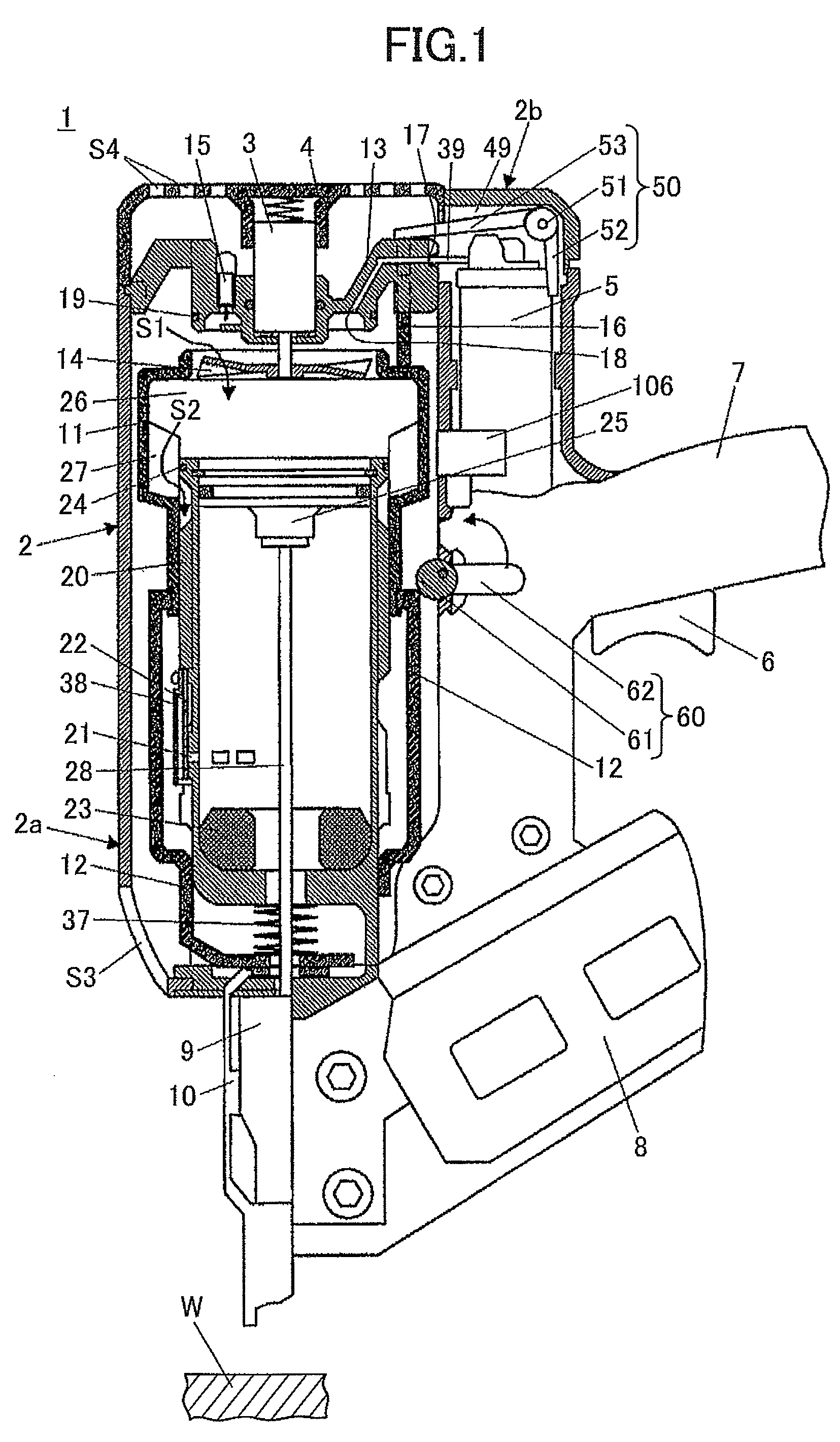
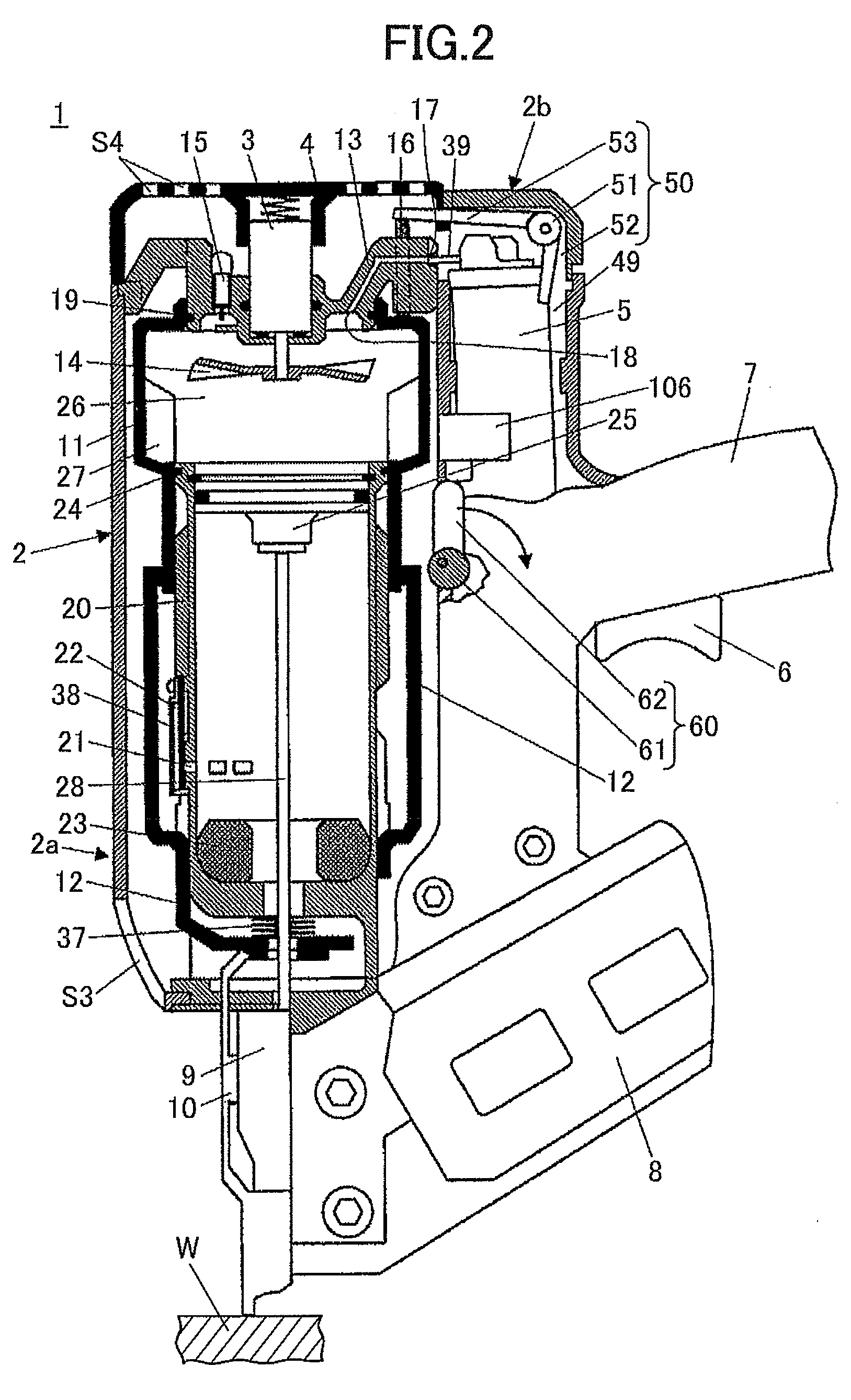
[0080]A combustion type power tool according to one embodiment of the present invention will be described with reference to FIGS. 1 through 3. In the drawings like parts and components are designated by the same reference numbers and will not be described repeatedly. Similarly, the components identical in function to those of the conventional combustion type power tool shown in FIG. 4 and FIG. 5 are designated by the same reference numbers. Further, the direction in which nails (fasteners) are driven by the combustion type power tool will be referred to as “lower” or “lower portion”, and the direction opposite to this direction will be referred to as “upper” or “upper portion” for the sake of convenience. The embodiment pertains to a nail gun that is one of the typical examples of the combustion type power tool.

[0081]An overall configuration of nail gun 1 will be described. As shown in FIG. 1, a nail gun 1 includes a housing 2 that constitutes an outer frame. The housing 2 includes ...


PUM

PropertyMeasurementUnit
Poweraaaaaaaaaa

Abstract

A combustion type power tool capable of avoiding wasteful injection of combustible gas from a gas canister even if an unintentional operation of the push lever takes place, and capable of avoiding wasteful electric power consumption even if a battery used as power supply remains set in the tool. While the tool is not being used, a stop unit is set at a stop position, preventing a gas canister from injecting gas, and while the tool is being used, the stop unit is set at a release position, allowing the gas canister to inject gas as a result of movement of a combustion chamber frame.

Description

TECHNICAL FIELD[0001]The present invention relates to a combustion type power tool, and more particularly, to a type thereof in which liquefied gas filled in a gas canister is injected into a combustion chamber, mixed with air and ignited, thereby generating driving force for moving a piston to drive fasteners such as nails, rivets and staples and the like.BACKGROUND ART[0002]As shown in FIG. 4, a portable combustion type power tool 90 generally includes a housing 2, a cylinder 20, a piston 25, a driver blade 28, a chamber head 13, a combustion chamber frame 11, a canister housing 49, a fan 14, an ignition plug 15, and a trigger switch 6. The housing 2 contains various components. The cylinder 20 is provided in the housing 2. The piston 25 is slidably movable in the cylinder 20 in an axial direction thereof. The driver blade 28 is fixed to the piston 25 and drives fasteners into a workpiece W as the piston 25 moves. The chamber head 13 is spaced from an end of the cylinder 20, and i...

Claims


Application Information

Patent Timeline
IPC IPC(8): B25C1/08
CPCB25C1/08
Inventor OHMORI, YASUKI
Owner HITACHI KOKI CO LTD
Why Eureka
Try Eureka