Variably controlled adjustable height carriages for raising, lowering, holding, locking and releasing objects on elevated structures

Inactive Publication Date: 2009-04-09
HOGAN JAMES
View PDF7 Cites 46 Cited by
  • Summary
  • Abstract
  • Description
  • Claims
  • Application Information

AI Technical Summary

Benefits of technology

[0009]To solve one or more of the problems set forth above, in an exemplary implementation of the invention, a variably controlled

Problems solved by technology

Unfortunately, such poles typically do not provide means for raising, lowering and easily removing the supported object.
Thus, installation and maintenance requires the use of a ladder, crane or other personnel lifting device, which is inconvenient, costly and conducive to injury.
There is an absence of versatile carriage systems that can lift, lock in place, and lower a wide array of light, medium or heavy objects on tall elongated structures, such as poles.
While such systems are useful for raising and lowering suspended lighting assemblies and their associated electrical wiring, such systems are not useful for plants that require irrigation.
Also, when lowered, the carried assemblies are not readily removable from the mast.
Furthermore, such systems typically require raising and lowering of high voltage electrical lines, which tend to wea

Method used


Image

  • Variably controlled adjustable height carriages for raising, lowering, holding, locking and releasing objects on elevated structures
  • Variably controlled adjustable height carriages for raising, lowering, holding, locking and releasing objects on elevated structures
  • Variably controlled adjustable height carriages for raising, lowering, holding, locking and releasing objects on elevated structures

Examples


Embodiment Construction

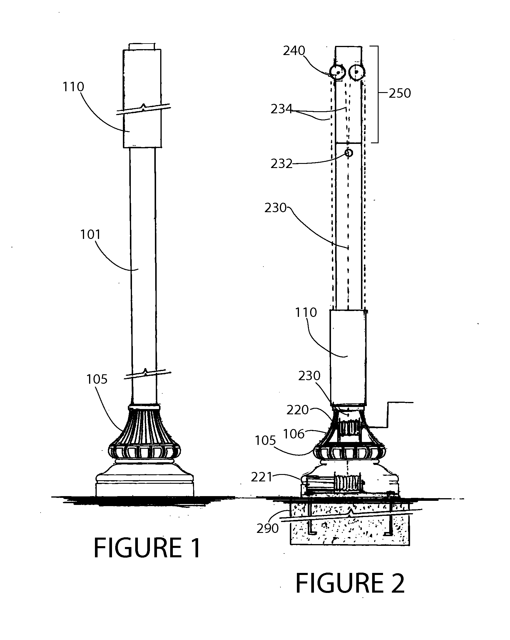
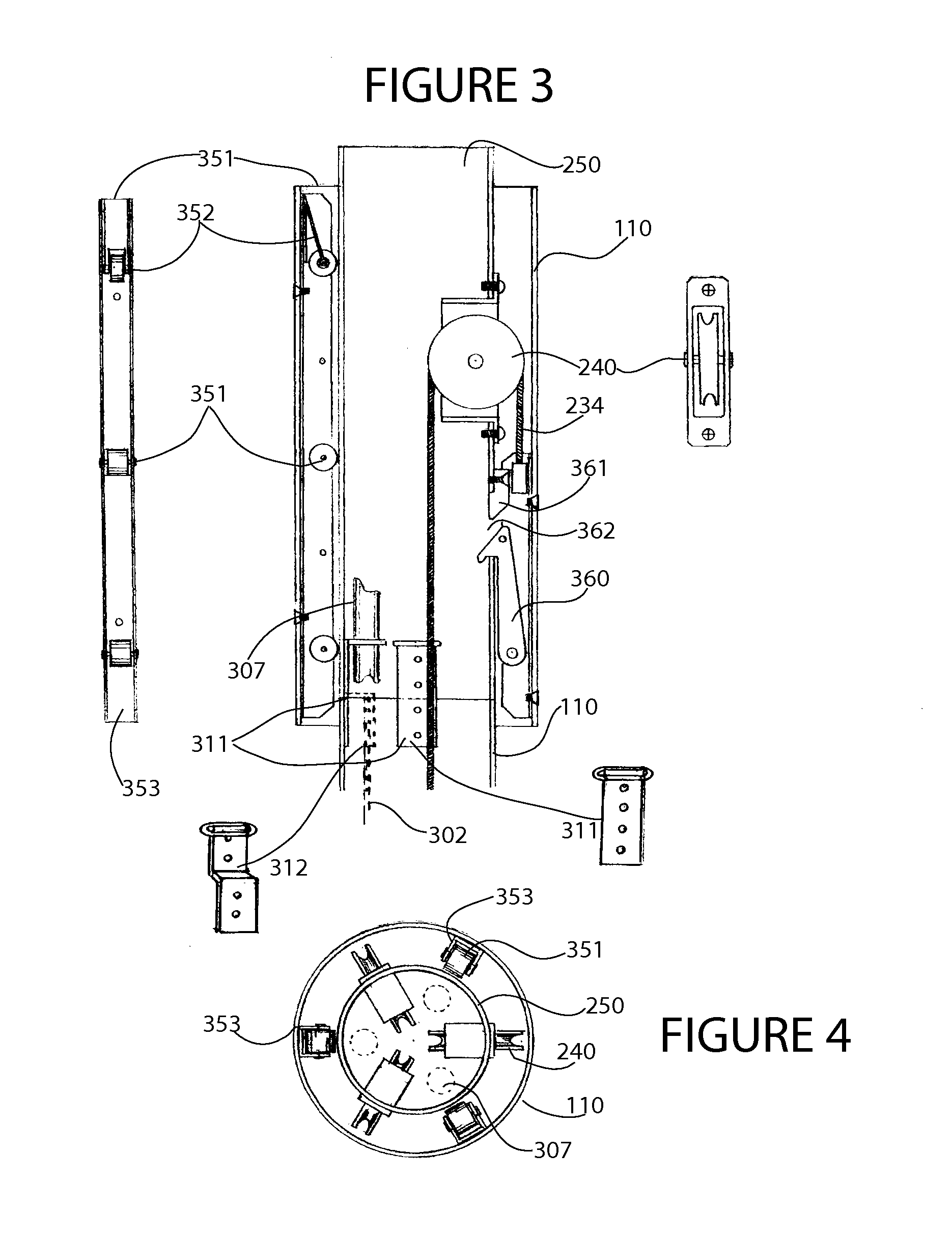
[0088]With reference to the Figures and the description provided below, an exemplary variable controlled carriage allowing for the raising, lowering, holding, locking and releasing of ornamental and utilitarian objects on poles or other elongated or elevated structures according to principles of the invention includes an adjustable height carriage, a vertical support having a top end and a bottom end, and means for controllably adjusting the height of the carriage relative to the support along a continuum of positions, from a lowest position to a highest position. In one embodiment, the means for controllably adjusting the height includes at least one pulley, which may define the highest position, and a tether guided by the pulley. In another embodiment, the means for controllably adjusting the height includes a winch (or windlass) operably coupled to the tether and adapted to retract (i.e., wind) and extend (i.e., unwind) the tether. The winch includes a control means, such as a ha...


PUM


Abstract

A system for raising and lowering a wide range of objects on an elongated tubular structure includes a carriage subsystem with a tubular body having an interior central channel an inner diameter greater than the outer diameter of the elongated tubular structure. Rollers facilitate linear translation of the tubular body along the elongated tubular structure. At least one hook is pivotally mounted on the tubular body and configured to controllably engage a means for locking the carriage in a raised position. The carriage subsystem also includes a flange for attaching an object to the carriage subsystem. A winch and cable control motion of the carriage system between a lowered position adjacent to the base and a raised position adjacent to the top of the tubular structure. A collar attached to the top of the tubular structure includes a tubular body with an outer diameter less than the inner diameter of the tubular body of the carriage subsystem. At least one slot is formed in the tubular body of the collar and configured for controllable engagement by the hook pivotally mounted on the tubular body in the interior central channel of the carriage subsystem. At least one pulley is rotatably mounted to the tubular body of the collar and configured for guiding a lanyard attached to the carriage subsystem at one end of the lanyard. An irrigation subsystem may be provided to irrigate supported planters. An electrical subsystem comprising aligned electrode assemblies may also be provided to supply electric power to an electrical load supported by the carriage when the carriage is locked in the raised position.

Description

RELATED APPLICATION[0001]This application is a continuation in part and claims the benefit of priority of U.S. Nonprovisional application Ser. No. 11 / 868,534, filed Oct. 8, 2007, the entire contents of which are incorporated herein by this reference, and a continuation in part and claims the benefit of priority of U.S. Nonprovisional application Ser. No. 12 / 026,553 filed Feb. 2, 2008, the entire contents of which are incorporated herein by this reference.FIELD OF THE INVENTION[0002]This invention generally relates to ornamental and utility poles, and, more particularly, to variable controlled carriages allowing for the raising, lowering, holding, locking and releasing of ornamental and utilitarian objects on poles or other elongated structures.BACKGROUND[0003]Utility and ornamental poles are well known in the art. Some poles are used to display signs, flags, banners, bird houses, nests, feeders and / or plants. Others are used to support communication systems, lights and security came...

Claims


Application Information

Patent Timeline
IPC IPC(8): B66D1/00B66F13/00A01G25/00
CPCA01G9/022A47G7/044A47G7/041A01G27/003F21V21/38
Inventor HOGAN, JR., JAMES
Owner HOGAN JAMES
Why Eureka
Try Eureka