Method for generating 3D building models from a set of floor plans

a technology of floor plans and 3d building models, applied in the field of rendering 3d drawings from floor plans, can solve the problems of time required, no system that uses simple data, and the inclusion of 3d building models, and achieve the effect of simple system and rapid and accurate orientation

Inactive Publication Date: 2009-04-09
HONEYWELL INT INC
View PDF0 Cites 11 Cited by
  • Summary
  • Abstract
  • Description
  • Claims
  • Application Information

AI Technical Summary

Benefits of technology

[0004]Accordingly, one advantage of the present invention is to provide a system and method for producing 3D models of buildings for building owners to have on hand in the event of a fire or other emergency in order to orient first responders.
[0005]Another advantage of the present invention is to provide a simple system and method for producing 3D models directly from floor plans by approximating the actual building, including floors and roofs.
[0007]It has now been discovered that the above and other advantages of the present invention may be obtained in the following manner. In its simplest form, the present invention comprises a system and method for producing 3D models of buildings from floor plans using a conversion algorithm. The 3D model assists persons needing to enter the building to be quickly and accurately oriented as to the location of items on various floors.
[0008]The conversion algorithm works in three steps. The first step generates one presence map for each floor plan. The maps are electronic renditions that may be taken from other electronic files or from scanned paper or hard copy plans, or otherwise imported into the processor. The maps are two dimensional grids indicating which pixels are exterior to the building and which are interior. The second step determines which interior elements in the presence maps represent floor and which represent roof. The final step renders the building in 3D from the presence maps.
[0009]In the preferred embodiment, the algorithm of this invention begins populating the presence map by considering each pixel in the floor plan, although any pixel can be the first one considered. The algorithm considers neighbor pixels as being each pixel directly up, down, left and right of the pixel being examined. The algorithm is also valid when neighbors further include pixels located diagonally from the pixel being examined, but will treat pixels as outside when wall-lines are too narrow.

Problems solved by technology

The key factor in limiting the inclusion of 3D building models in commercial first response systems is the time required to commission a system involving a 3D model.
To date, no system has been proposed that uses simple data, such as the respective floor plans of a building or other structure, to translate directly into a 3D model.

Method used


Image

  • Method for generating 3D building models from a set of floor plans
  • Method for generating 3D building models from a set of floor plans
  • Method for generating 3D building models from a set of floor plans

Examples


Embodiment Construction

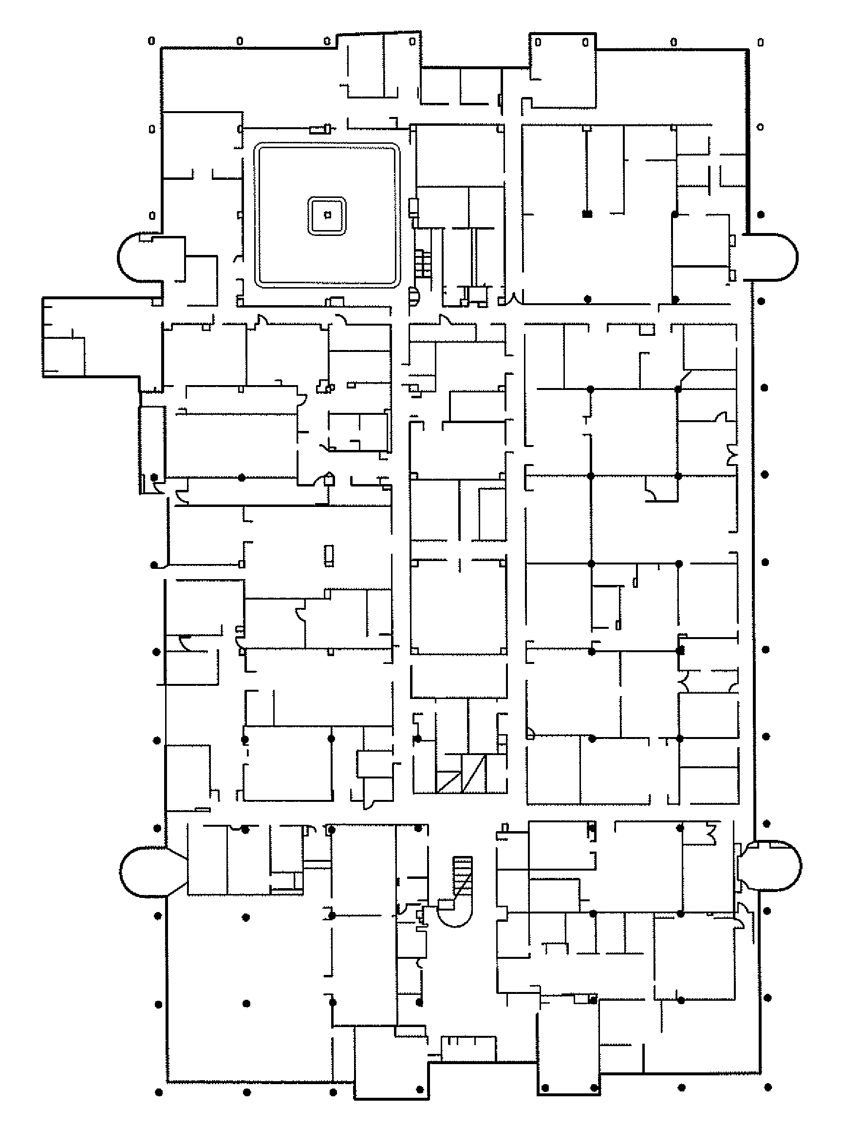
[0017]As shown in the drawings, this invention produces a 3D rendition of a building or other structure from 2D floor plans or other drawings. The floor plans, shown in FIG. 1 as a typical floor plan, has areas inside and outside the structure, with interior walls and exterior features such as a canopy over an entrance.

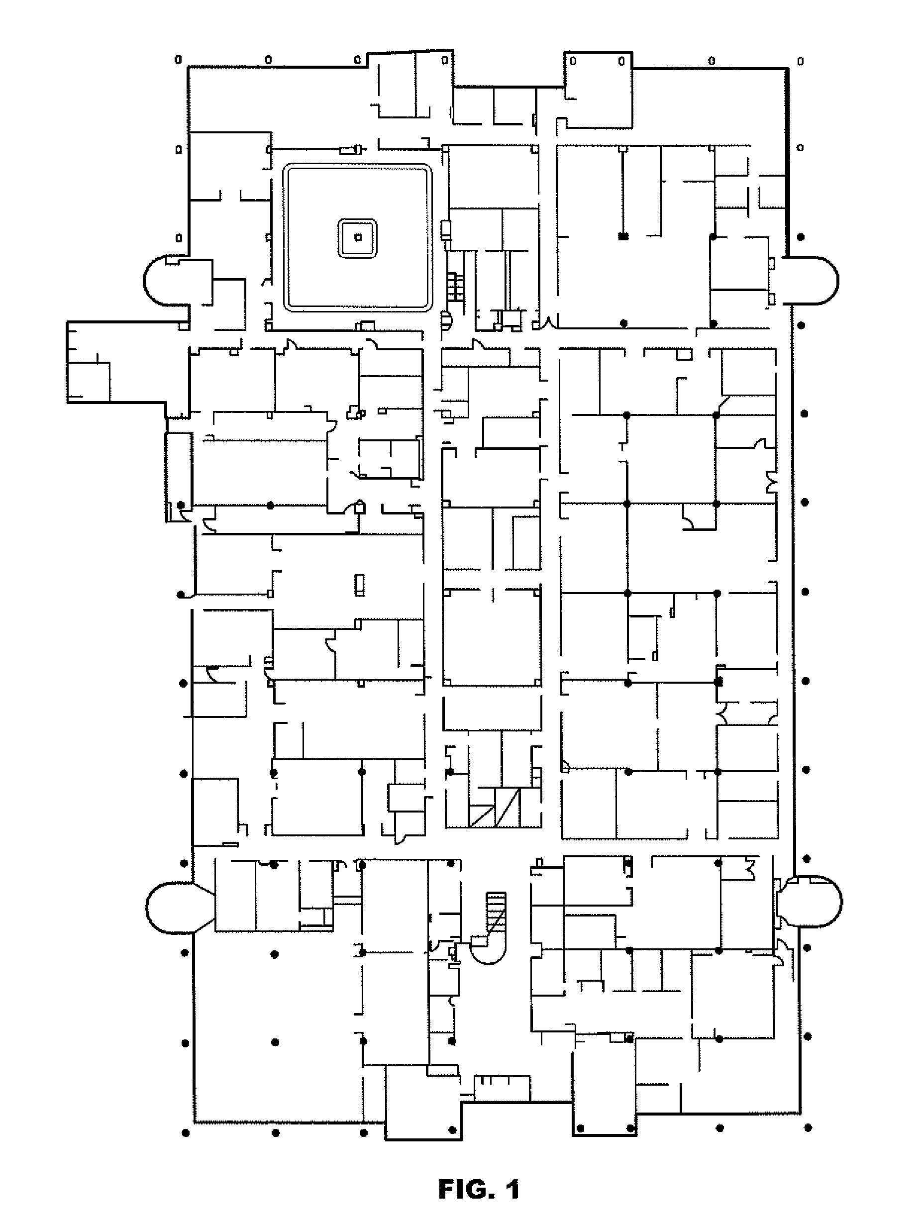
[0018]An electronic form of the floor plan in pixels is generated by a computer or processor, either by scanning hand drawings, using Computer Assisted Drafting programs or by other conventional methods of producing electronic renditions of a 2D figure or drawing. A presence map is generated for each floor plan, such that the maps are 2D grids indicating which pixels are exterior to the building and which are interior. Next the pixels are examined to determine which interior elements in the presence maps represent floor and which are roof. The presence maps for all the floors are combined by the computer into the resulting 3D model as shown in FIG. 3.

[0019]Each presen...


PUM


Abstract

A method and system of generating 3D models from a set of 2D floor plans using an algorithm to classify pixels from each floor plan as outside or inside. Inside pixels are drawn as horizontal rectangles and walls are drawn as vertical rectangles. When a floor is compared to the one below and the pixel below is interior and the pixel above is exterior, it is marked as a roof pixel.

Description

FIELD OF THE INVENTION[0001]The present invention relates to rendering 3D drawings from floor models. More particularly, the present invention relates to a system which converts a plurality of floor plans for a building into a 3D version.BACKGROUND OF THE INVENTION[0002]Techniques for rendering building models in 3D have been experimentally shown to improved the performance of firefighter and other first responder in making an initial assessment of a scene. The key factor in limiting the inclusion of 3D building models in commercial first response systems is the time required to commission a system involving a 3D model.[0003]At the present time, 3D drawings of buildings are either hand drawn, such as by an architect or engineer, or are produced directly in a CAD (computer assisted drafting) program which requires a large amount of time and money. To date, no system has been proposed that uses simple data, such as the respective floor plans of a building or other structure, to transl...

Claims


Application Information

Patent Timeline
Patent Type & Authority Applications(United States)
IPC IPC(8): G06K9/00
CPCG06T17/10
Inventor RYE, JEFFREY M.
Owner HONEYWELL INT INC
Why Eureka
Try Eureka