
Auto-configuration and automation of a building management system

a technology of building management system and auto-configuration, applied in the field of building automation, can solve the problems of complex components and software tools, home automation systems, and continual setbacks

Active Publication Date: 2016-12-13
CRESTRON ELECTRONICS
View PDF21 Cites 42 Cited by
  • Summary
  • Abstract
  • Description
  • Claims
  • Application Information

AI Technical Summary

Benefits of technology

This patent is about a building management system that uses a virtual floor plan to control various devices in the building. The system can create the virtual floor plan by using recorded data sets and comparing them to each other. It can also create inner walls between control devices to prevent data sets from overlapping. The system can also monitor and report the status of the building in a user-friendly way without requiring manual setup. Overall, the patent provides a more efficient and seamless way to manage a building's devices.

Problems solved by technology

While home automation solutions are becoming increasingly available to an average consumer, they continue to suffer from many setbacks.
Many home automation systems implement complicated components and software tools, requiring a trained technician to install and configure the system.
Yet, home automation systems that are simple and easy to install and configure, only provide basic operations, lacking the high end features and control options available in more complex systems.

Method used


Image

  • Auto-configuration and automation of a building management system
  • Auto-configuration and automation of a building management system
  • Auto-configuration and automation of a building management system

Examples


Embodiment Construction

[0045]The embodiments are described more fully hereinafter with reference to the accompanying drawings, in which embodiments of the inventive concept are shown. In the drawings, the size and relative sizes of layers and regions may be exaggerated for clarity. Like numbers refer to like elements throughout. The embodiments may, however, be embodied in many different forms and should not be construed as limited to the embodiments set forth herein. Rather, these embodiments are provided so that this disclosure will be thorough and complete, and will fully convey the scope of the inventive concept to those skilled in the art. The scope of the embodiments is therefore defined by the appended claims. The detailed description that follows is written from the point of view of a control systems company, so it is to be understood that generally the concepts discussed herein are applicable to various subsystems and not limited to only a particular controlled device or class of devices, such as...


PUM


Abstract

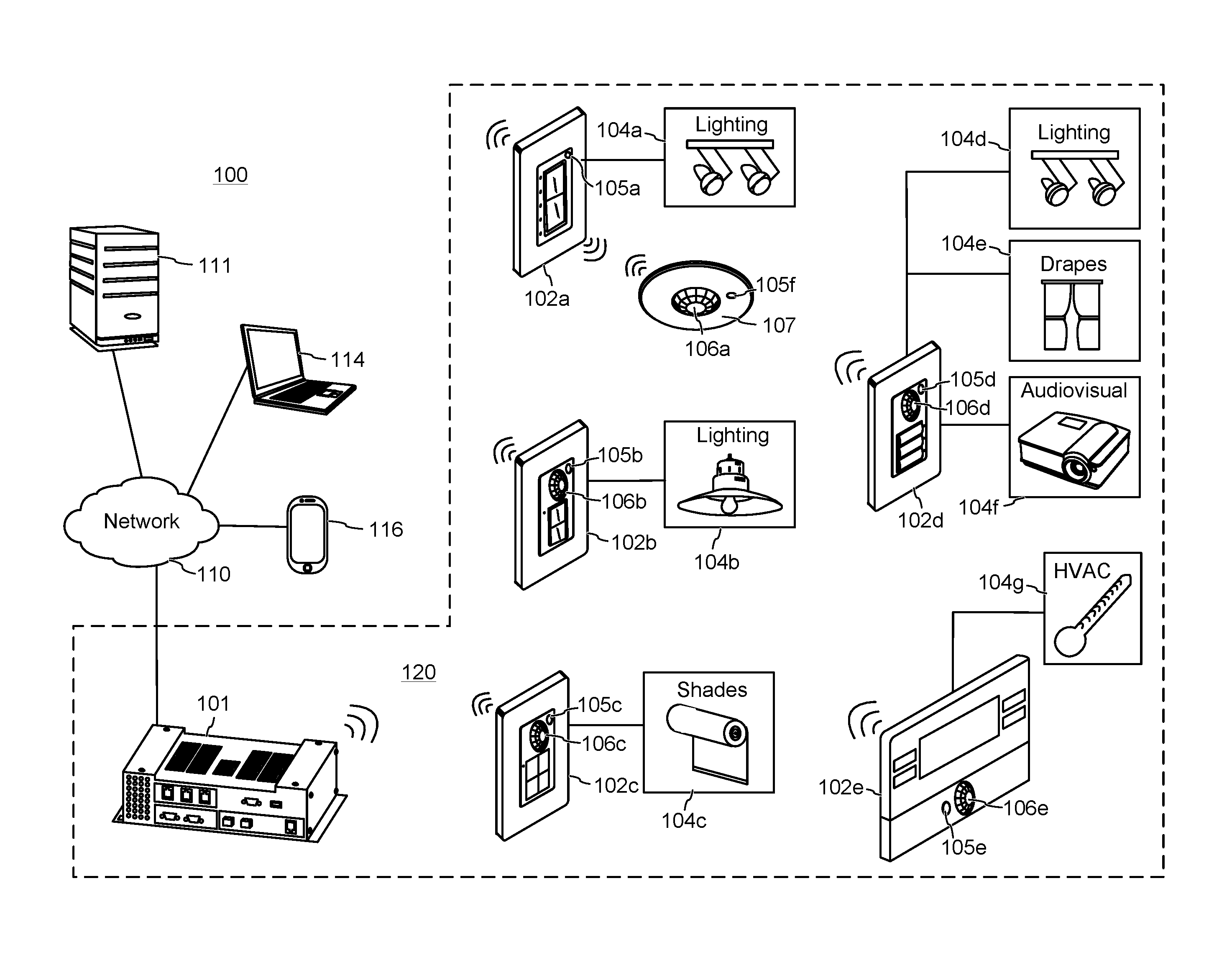
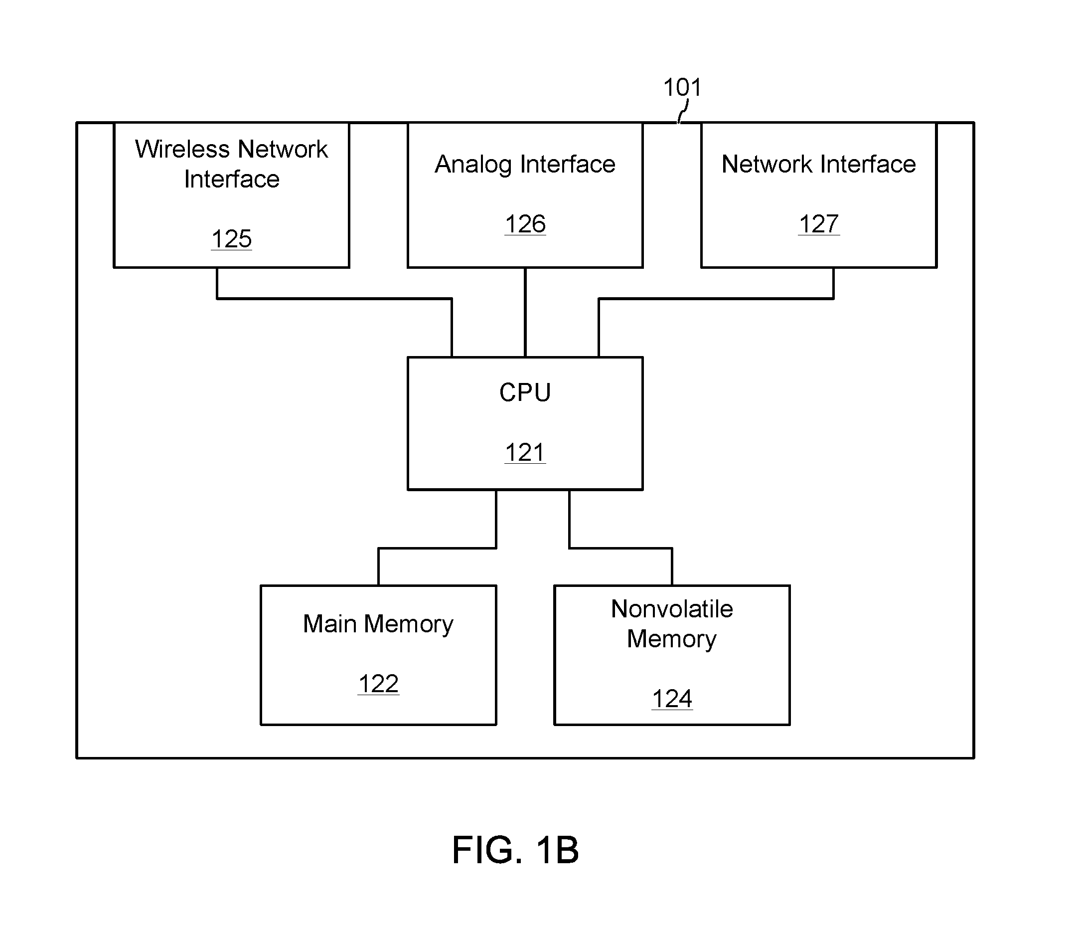
A building management system is disclosed that is automatically configured using a wireless mesh network data and sensor data to create a virtual floor plan. The building management system comprising a control processor, a plurality of lighting devices, and a plurality of control devices comprising lighting control devices, each directly controlling one or more of the lighting devices. The control devices intercommunicate with each other over a wireless network, and each control device comprises a light sensor detecting light intensity. The control processor creates the mesh graph of relative positioning of the control devices to each other using received wireless signal strengths of the control devices relative to each other. The control processor determines relative positioning of the lighting devices to the control devices using the mesh graph and received light intensity readings obtained by the light sensors of the control devices when each lighting device was turned on and off. The virtual floor plan comprises the relative positioning of the control devices to each other, the relative positioning of the control devices to the lighting devices, and room-by-room groupings of the plurality of control devices and the lighting devices.

Description

BACKGROUND OF THE INVENTION[0001]Technical Field[0002]Aspects of the embodiments relate to building automation, and more specifically to systems, methods, and modes for a building management system that is automatically configured using a wireless mesh network data and sensor data to create a virtual floor plan.[0003]Background Art[0004]Building automation is ever evolving to provide consumers with convenient and simple control and monitoring of various mechanical and electrical equipment within a building through building management systems (BMS), also known as building automation systems (BAS), and energy management systems (EMS). Building management systems provide comfort, convenience, simplicity and security, as well as lower energy costs. They utilize a network of control devices and sensors distributed throughout a residential or commercial building to control and provide information of the mechanical and electrical equipment within the building. For example, the system can c...

Claims


Application Information

Patent Timeline
Patent Type & Authority Patents(United States)
IPC IPC(8): H05B37/02H05B39/04H05B41/36H04W4/04H04L12/28H04W84/18H04M1/72415
CPCH04L12/2827H04W4/043H04L12/2807H04L2012/2841H04L2012/285H04W84/18H04L2012/2849H04L12/6418H05B47/19H05B47/11Y02B20/40H05B47/197H05B47/1995H05B47/1975H04W4/33H04M1/72415
Inventor SKEFFINGTON, MICHAEL
Owner CRESTRON ELECTRONICS
Learn More