Steering device, boarding type moving body with steering device, and steering method for moving body

Inactive Publication Date: 2009-04-09
TOYOTA JIDOSHA KK
View PDF5 Cites 5 Cited by
  • Summary
  • Abstract
  • Description
  • Claims
  • Application Information

AI Technical Summary

Benefits of technology

[0036]According to this steering method, by appropriately selecting and determining the threshold value for defining the width of the dead zone in accordance with the moving speed of the moving body, variations in operational forces obtained at operator's different sensible speeds can be absorbed. After the variations in the operational forces of the operator is reduced the movement of the moving body can be controlled in accordance with the force applied by the operator, and when the operator moves the moving body by an intuitive operation sufficient responsiveness and operability can be secured.
[0037]The control steps for controlling the amount of movement and the direction of movement based on a value obtained by multiplying the input physical quantity by a specific gain may further have a gain changing step of changing the magnitude of the gain in accordance with a speed at which the moving body moves. According to this steering method, for example, the controller may change the gain more significantly as the speed of the moving body becomes higher. Consequently, the responsiveness of the rotational angle (steering angle) that is obtained at the time of moving at high speeds can be improved, and therefore the effect of an easy operation that can avoid obstacles during a high-speed operation can be achieved.
[0038]This steering method may further have a step of

Problems solved by technology

It is generally known that, when experimentally extracting operational forces of a plurality of operators during the initial stage of the movement (the time between the

Method used


Image

  • Steering device, boarding type moving body with steering device, and steering method for moving body
  • Steering device, boarding type moving body with steering device, and steering method for moving body
  • Steering device, boarding type moving body with steering device, and steering method for moving body

Examples


Example

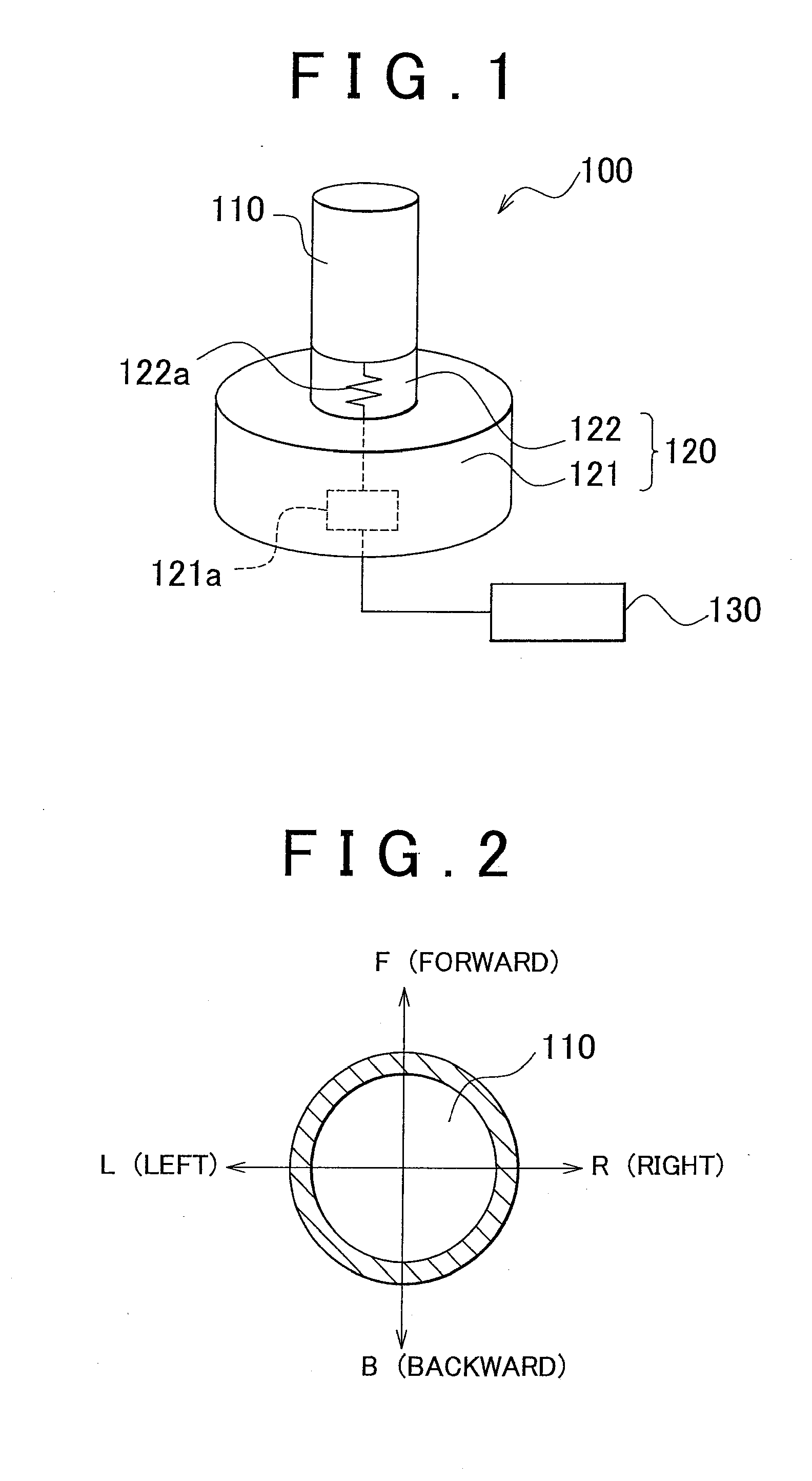
[0053]FIG. 1 is a diagram showing a steering device 100 according to the first embodiment of the invention. The steering device 100 has an operating part 110 operated by an operator, a base part 120 for supporting the operating part 110, and a controller 130 for controlling the amount of movement and the direction of movement of a moving body (not shown) corresponding to a steering target. The base part 120 has a base part main body 121, and an elastic body 122 for supporting the operating part 110 on the base part main body 121.

[0054]The operating part 110 has a rod-like member that extends in a vertical direction with respect to a paper surface. One end (lower end) of the rod-like member is fixed to the base part main body 121 via the elastic body 122 in a substantially vertical direction. The operator can deform the elastic body 122 by holding the rod-like member and inclining it in a specific direction with respect to the base part main body 121. For example, in FIG. 2 that show...

Example

[0073]A second embodiment of the invention is now described. Here, a boarding type moving body 10 in which the above steering device 100 is incorporated is described.

[0074]FIG. 10 is a conceptual diagram in which a conceptual model is used for showing a side of the inverted pendulum type moving body (to be simply referred to as “moving body” hereinafter) 10 that can be subjected to movement control by an operation performed by an occupant P in a state where the occupant P is placed as an operator. FIG. 11 is a schematic diagram of an internal structure of a control box 20 for controlling the moving body 10 shown in FIG. 10. As shown in FIGS. 10 and 11, the moving body 10 has a pair of two wheels 33, 34 facing each other, wherein rotary drive of each wheel is controlled such that the moving body keeps its inverted state while these wheels are in contact with a moving floor part. Note that the same numerals are used to represent the same elements having the same or similar configurati...


PUM


Abstract

A steering device for steering a moving body having moving means has: an operating part; a detecting part that detects a physical quantity based on a magnitude and direction of a force applied to the operating part; and a controller that drives the moving means based on the physical quantity detected by the detecting part and controls an amount of movement and a direction of movement of the moving body. The controller has a dead zone for controlling the amount of movement without receiving influence of the magnitude of the physical quantity until the physical quantity detected by the detecting part exceeds a predetermined threshold value, and determines the threshold value in accordance with a moving speed of the moving body.

Description

INCORPORATION BY REFERENCE[0001]The disclosure of Japanese Patent Application No. 2007-261595 filed on Oct. 5, 2007, including the specification, drawings and abstract is incorporated herein by reference in its entirety.BACKGROUND OF THE INVENTION[0002]1. Field of the Invention[0003]The invention relates to a steering device for steering a moving body, a moving body having the steering device, and a steering method of steering the moving body.[0004]2. Description of the Related Art[0005]There is a conventional circular steering device (handle) used in a general vehicle as a steering device for controlling the direction or amount of movement (speed, acceleration) of a moving body. This steering device not only determine the amount of movement in relation to the amount of operation carried out by an operator, but also determines the direction of movement of the moving body based on a steering direction. Such a circular steering device is connected directly to a steering rack by means ...

Claims


Application Information

Patent Timeline
IPC IPC(8): B62D6/00
CPCB62D37/00B62K3/007B62D61/00B62K11/007
Inventor WEISSERT, MICHAELIZUO, TAKASHI
Owner TOYOTA JIDOSHA KK
Why Eureka
Try Eureka