

Backwater valve assembly with removable valve member
- Summary
- Abstract
- Description
- Claims
- Application Information
AI Technical Summary
Problems solved by technology
Method used
Image

Examples
Embodiment Construction
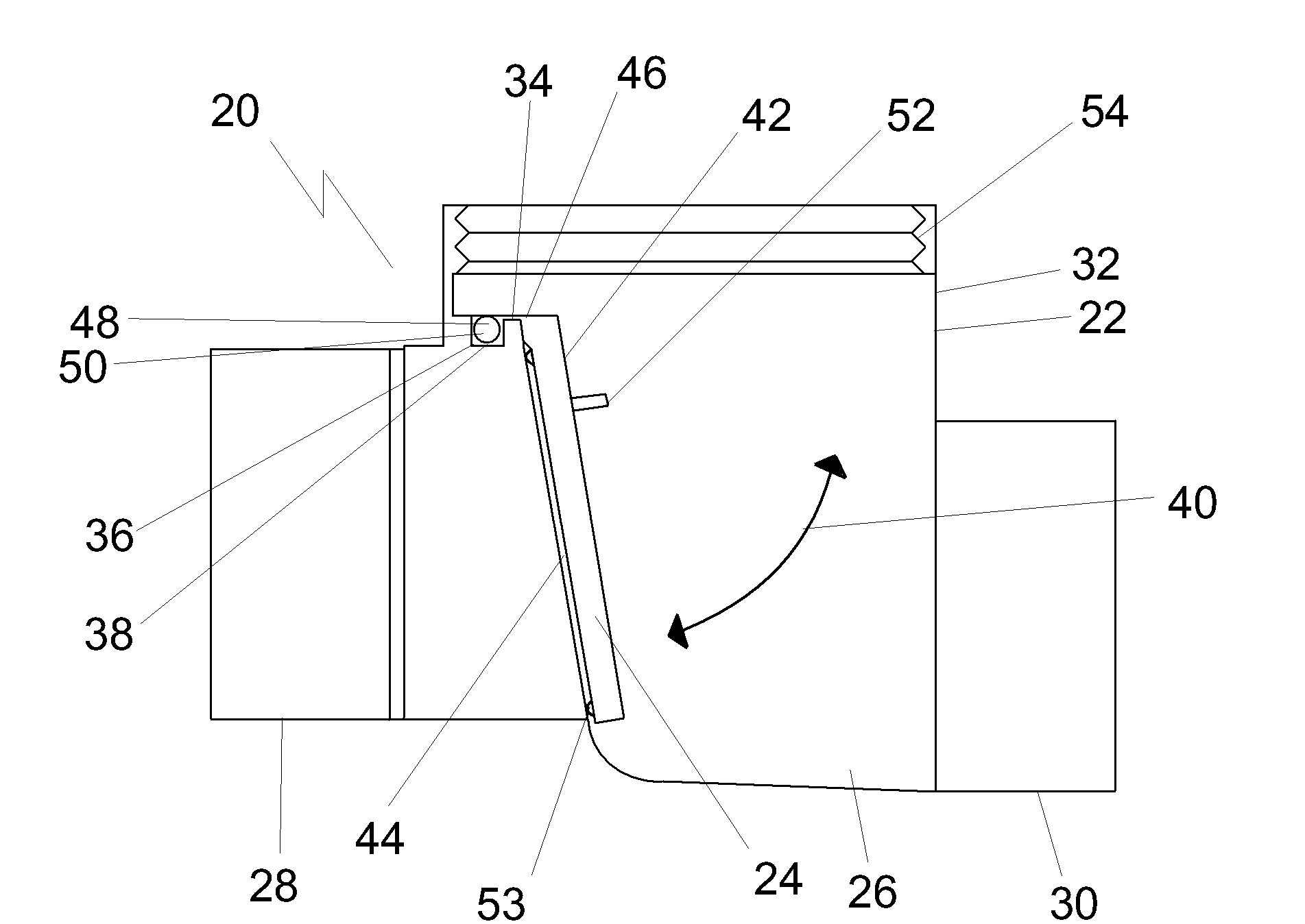
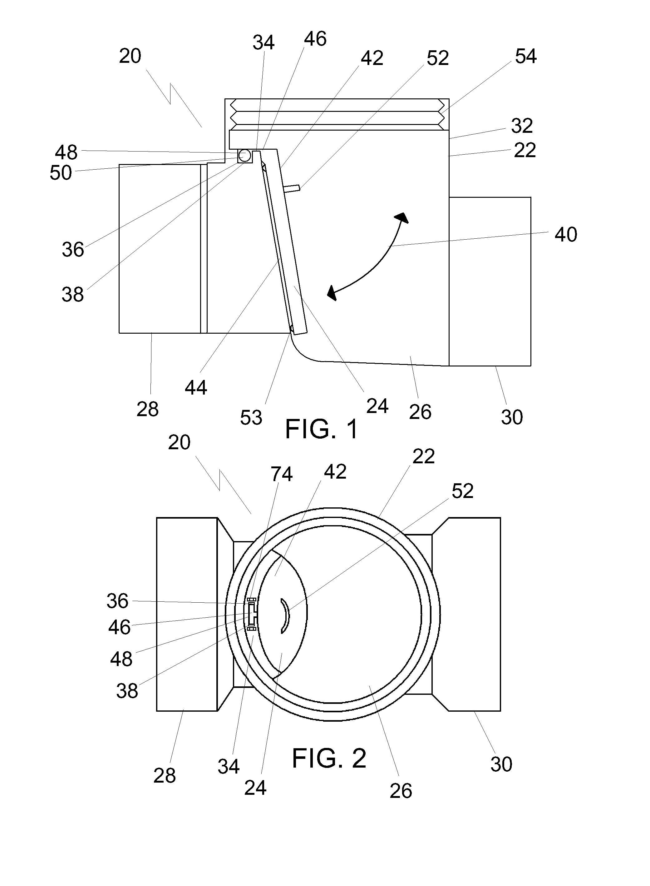
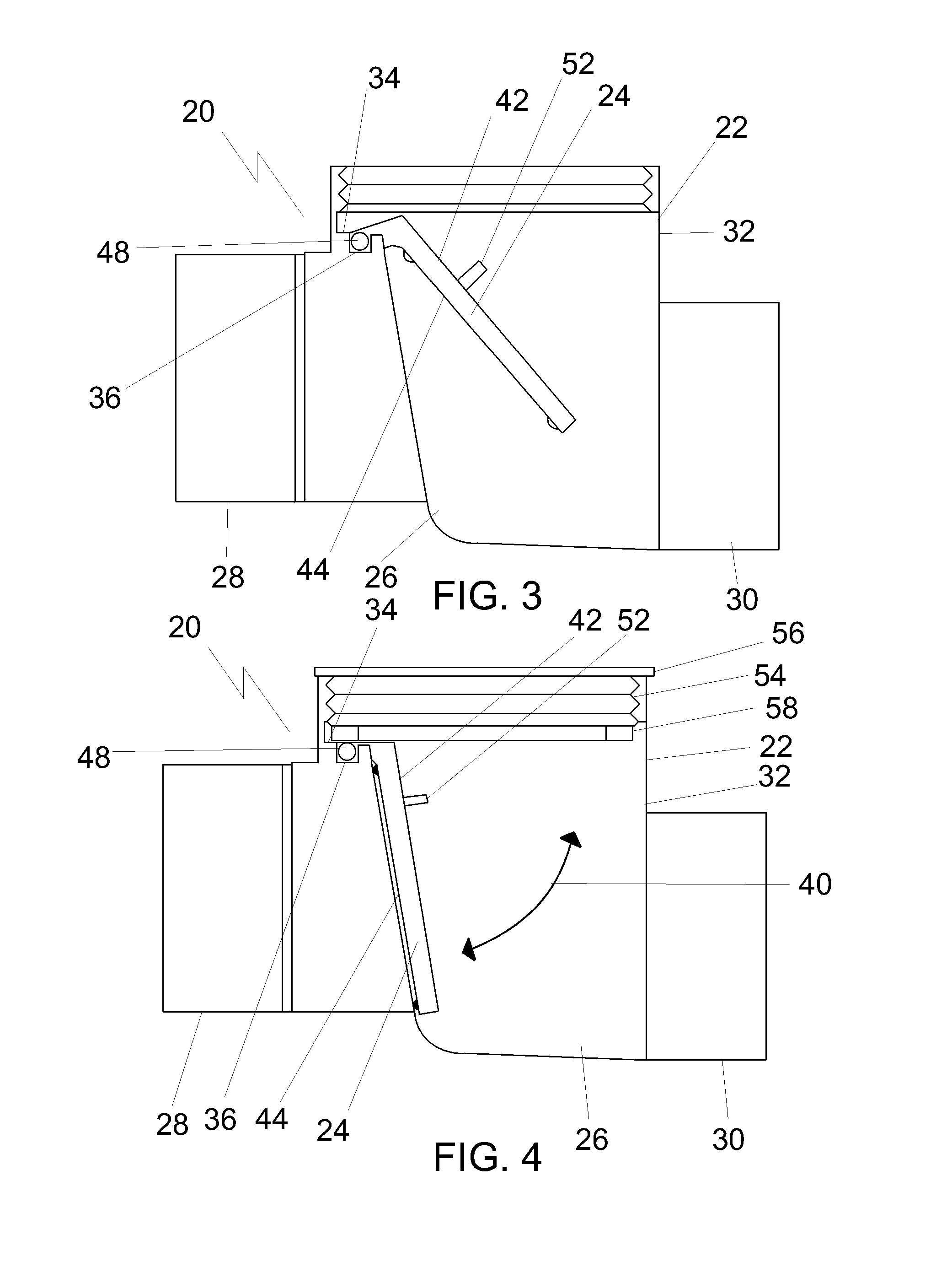
[0018]The preferred embodiment, a backwater valve assembly generally identified by reference numeral 20, will now be described with reference to FIG. 1 through 12.
[0019]Structure and Relationship of Parts:
[0020]FIG. 1 shows backwater valve assembly 20, consisting of a housing 22 and a valve member 24. Housing 22 has an interior 26, an inlet 28 to interior 26, an outlet 30 to interior 26 and a riser 32 providing servicing access to interior 26. Housing 22 also contains an internal ledge 34 within interior 26, on which is positioned a retainer clip 36 oriented in vertical alignment with the riser 32. Retainer clip 36 may consist of a swivel guide slot 38, as shown in FIG. 1-2. Referring to FIG. 1, valve member 24 is adapted to be pivotally positioned across inlet 28 of housing 22 so that liquid flows in through inlet 28 and out through outlet 30, but any reversal of flow is prevented by the positioning of valve member 24. A path of movement 40 of valve member 24 through housing 22 is ...
PUM
 Abstract
Description
Claims
Application Information