Dispenser nozzle having differential hardness

a technology of dispensing nozzle and differential hardness, which is applied in the direction of liquid transferring device, transportation and packaging, packaging, etc., can solve the problems of long-term variation in droplet volume, rapid deterioration of valve seat and surrounding surfaces, and accelerated wear at these locations

Inactive Publication Date: 2009-04-16
NORDSON CORP
View PDF8 Cites 64 Cited by
  • Summary
  • Abstract
  • Description
  • Claims
  • Application Information

AI Technical Summary

Problems solved by technology

Control of the droplet-to-droplet volume is critical to the quality and cost of the overall process.
However, long-term variation in droplet volume often occurs due to wear within the dispensing system, particularly within the nozzle which is in continuous and direct contact with materials while

Method used


Image

  • Dispenser nozzle having differential hardness
  • Dispenser nozzle having differential hardness
  • Dispenser nozzle having differential hardness

Examples


Embodiment Construction

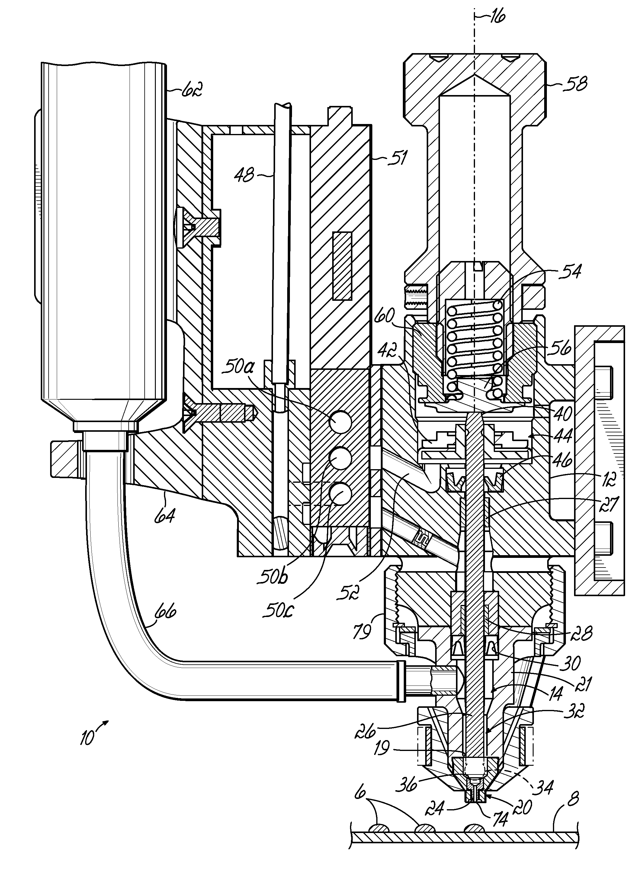
[0016]FIG. 1 depicts an exemplary jet dispenser 10 configured to form droplets 6 of material and project them toward a substrate 8. Generally, the viscous material may be any highly-viscous material including, but not limited to, solder flux, solder paste, adhesives, solder mask, thermal compounds, oil, encapsulants, potting compounds, inks, silicones, or visco-elastic fluids. In the embodiment shown, substrate 8 is moved in one direction to control the placement of droplets 6 on the substrate 8. It will be appreciated, however, that the jet dispenser 10 may alternatively be moved relative to the substrate 8. Examples of a jet dispenser is shown and described in co-pending PCT Application US 2004 / 020247 (Publication No. WO 2005 / 009627) filed Jun. 25, 2004, although it will be recognized that various other types of jet dispensers could be used as well, and the principles as disclosed herein are not limited to use with the particular jet dispenser illustrated and described. PCT Applic...


PUM


Abstract

A jet dispenser includes a fluid chamber body that includes a fluid chamber. A nozzle assembly is removably coupled to the fluid chamber body. The nozzle assembly includes a hub and an insert. The hub cooperates with the fluid chamber body to form a portion of the fluid chamber. A valve member is movably disposed within the fluid chamber. The insert is positioned at least partially within the hub. The insert includes a valve seat, a discharge passage, and an exit orifice at a distal end of the discharge passage. The valve seat is harder than the hub. The valve member selectively contacts the valve seat to dispense droplets of viscous material from the exit orifice.

Description

FIELD OF THE INVENTION[0001]The present invention generally relates to viscous material dispensing apparatuses, and more particularly to a non-contact jet dispenser for dispensing discrete amounts of viscous material to a substrate.BACKGROUND OF THE INVENTION[0002]Dispensing systems have become an integral part of the electronics manufacturing process for depositing underfill, encapsulants, solder fluxes, surface mount adhesives, conformal coatings, and other materials onto a substrate, such as a printed circuit board. Each dispensing system used in the electronics manufacturing process has a particular dispensing characteristic that is determined in large measure by the desired dispense pattern on the substrate, the flow rate and / or viscosity of the dispensed material, and the desired electronic component assembly throughput through the dispensing system.[0003]For example, in the assembly of ball grid arrays (BGAs) and other electronic components onto a ceramic or flame-retardant, ...

Claims


Application Information

Patent Timeline
IPC IPC(8): B05B1/30A62C37/20A62C31/02
CPCB05C5/001B05C11/1034B05C5/0237
Inventor AHMADI, MANIFISKE, ERIK A.
Owner NORDSON CORP
Why Eureka
Try Eureka