Dual band radio frequency transmitter

a radio frequency transmitter and dual band technology, applied in the field of radio frequency communication, can solve the problems of increasing the cost and size (e.g., the integrated circuit die area) of the wireless communication device to support dual band

Active Publication Date: 2009-04-16
QUALCOMM INC
View PDF10 Cites 26 Cited by
  • Summary
  • Abstract
  • Description
  • Claims
  • Application Information

AI Technical Summary

Problems solved by technology

However, two separate transmit signal paths increase the cost and size (e.g., integrated circuit die area) of the wireless communication device to support dual band capability.

Method used


Image

  • Dual band radio frequency transmitter
  • Dual band radio frequency transmitter
  • Dual band radio frequency transmitter

Examples


Embodiment Construction

[0022]The following description and drawings are illustrative of the invention and are not to be construed as limiting the invention. Numerous specific details are described to provide a thorough understanding of the present invention. However, in certain instances, well-known or conventional details are not described in order to avoid obscuring the description of the present invention. References to one embodiment or an embodiment in the present disclosure are not necessarily to the same embodiment, and such references include one or more embodiments.

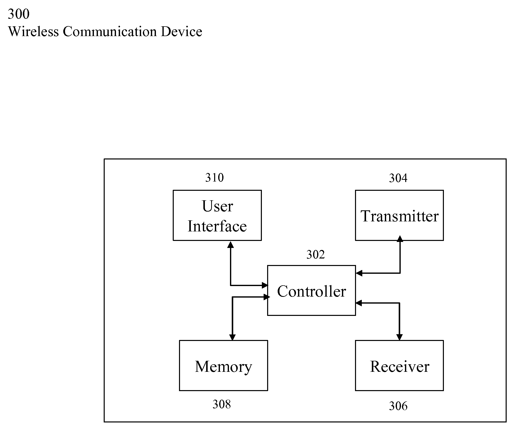
[0023]FIG. 3 illustrates a block diagram representation of a wireless communication device 300, according to one aspect of the present invention. The device 300 may be any type of device such as, for example, a cellular telephone, otherwise referred to as a mobile telephone, a cell phone, a radio telephone, a portable phone, mobile station, cordless phone, etc. The device 300 may employ any type of wireless technology using any part of...


PUM


Abstract

A transmitter includes a transformer and a transformer tuning circuit. The transformer transforms a differential radio frequency (RF) signal to a single-ended RF signal. The transformer tuning circuit tunes the transformer to permit the transmitter to transmit the single-ended RF signal in a first frequency band (e.g., cellular frequency band) or a second frequency band (e.g., PCS frequency band).

Description

FIELD OF THE INVENTION[0001]The present invention generally relates to radio frequency communications. More particularly, the present invention relates to a dual band radio frequency transmitter.BACKGROUND OF THE INVENTION[0002]Advances in technology for wireless communication devices, such as cellular telephones, enable characteristics, such as cost, size, weight, and power, of the devices to be reduced while maintaining or improving performance standards of the devices, thereby improving the portability of the devices to the point where the devices are now commonly used as a replacement for conventional landline telephones.[0003]One effective approach to reducing the cost and size of wireless communication devices is to use the same component for more than one function of a device. This approach may be known as increasing component integration or circuit reuse.[0004]While the advances have improved the portability of the devices, consumers of the devices continue to demand more fu...

Claims


Application Information

Patent Timeline
Patent Type & Authority Applications(United States)
IPC IPC(8): H04B1/38
CPCH04B1/0067H04B1/0483H04B1/0458
Inventor DENG, JUNXIONGBHAGAT, MAULIN PARESHBHAISAHOTA, GURKANWAL SINGH
Owner QUALCOMM INC
Why Eureka
Try Eureka