
Dynamic heat exchanger

Inactive Publication Date: 2009-04-23
KMB
View PDF25 Cites 6 Cited by
  • Summary
  • Abstract
  • Description
  • Claims
  • Application Information

AI Technical Summary

Benefits of technology

[0007]Other objects, features, functionality and characteristics of the present invention, as well as the methods of operation and the functions of the related elements of the structure, the combination of parts and ec

Problems solved by technology

Although these materials have high heat capacity, they are not suitable for quickly accumulating heat from the first flow medium and then quickly transferring the heat to the second flow medium.

Method used


Image

  • Dynamic heat exchanger
  • Dynamic heat exchanger
  • Dynamic heat exchanger

Examples


Embodiment Construction

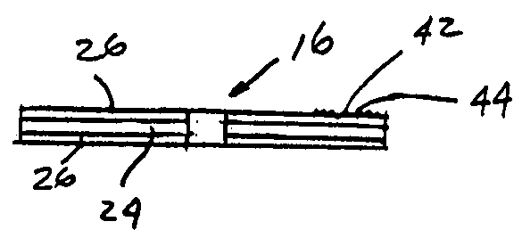
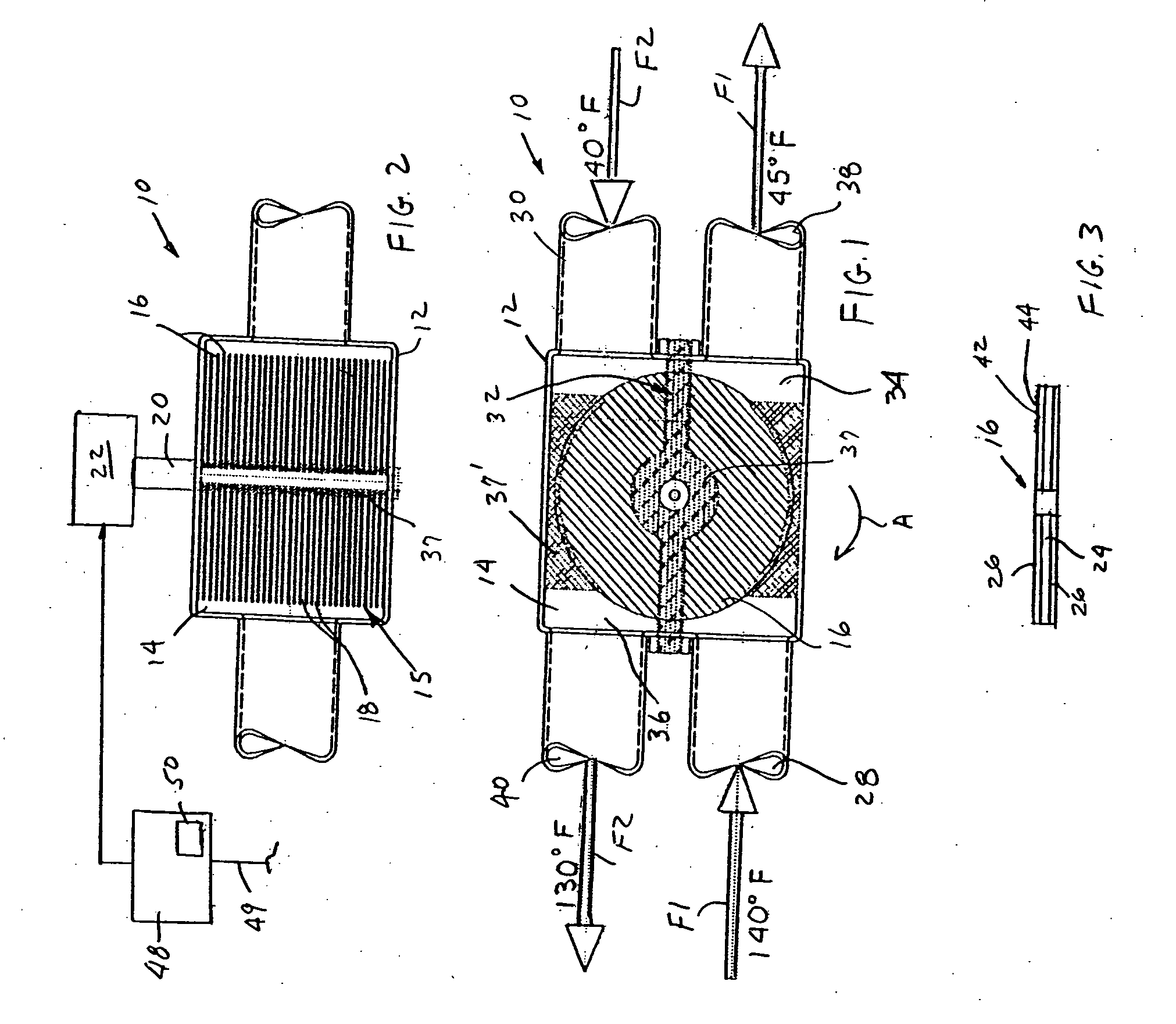
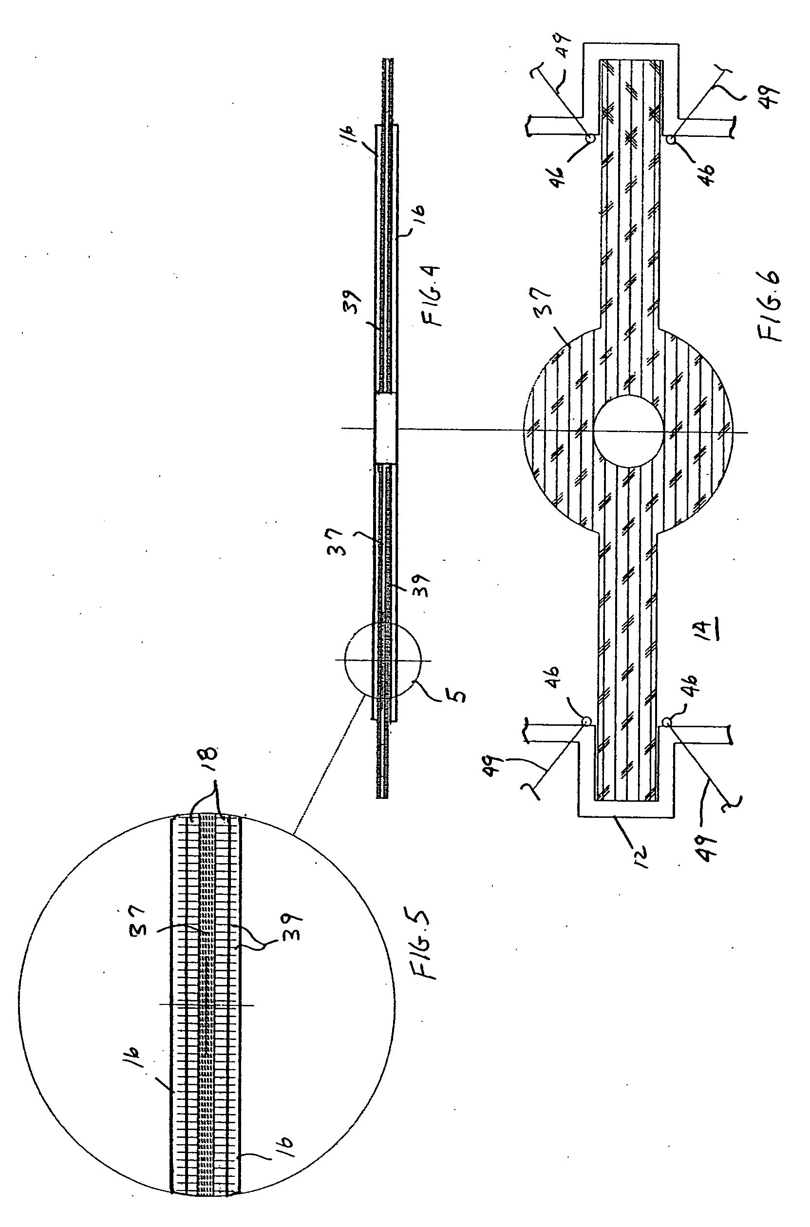
[0015]With reference to FIGS. 1 and 2, a rotary heat exchanger for heat exchange between at least two fluids is shown, generally indicated at 10, in accordance with an embodiment of the invention. The rotary heat exchanger 10 includes a housing 12 defining an interior space 14. Heat transfer structure, generally indicated at 15, is provided in the interior space 14 and in the embodiment is in the form of a plurality of concentric, plate-shaped members or discs 16 disposed in spaced relation to define passageways 18 (FIG. 2) between the discs. Each disc 16 is mounted for rotation within the housing. More particularly, with reference to FIG. 2, each disc 16 is coupled with a common shaft 20 that is rotated by a motor 22. Each disc 16 is coupled at central portion thereof to the shaft 20. The shaft 20 can be part of the motor 22 or coupled with a shaft of the motor 22. The discs 16 can be a structure made from a single material having high thermal conductivity (e.g., copper). However, ...


PUM


Abstract

A rotary heat exchanger includes a housing defining an interior space and heat transfer structure in the interior space. The heat transfer structure includes a plurality of concentric discs disposed in spaced relation to define passageways between the discs. The discs are mounted for rotation within the housing. Partition structure divides the interior space into first and second chambers. When heat transfer structure is rotated and first and second fluids are introduced into the associated chambers and between the passageways, with the first fluid having a temperature greater than a temperature of the second fluid, the discs are rapidly heated thereby removing heat from the first fluid and heating the second fluid.

Description

FIELD OF THE INVENTION[0001]The invention relates to fluid heat exchangers and, more particularly, to regenerative heat exchangers that rotate and have two separated chambers through which respective heat supplying and heat receiving fluids circulate.BACKGROUND OF THE INVENTION[0002]U.S. Pat. No. 4,491,171 discloses a regenerative type heat exchanger having a cylindrical roller that rotates. Two media flows are separated by a divider wall. A first media flow supplies heat and the heats the wall of the roller as the media flow passes through the wall. Since the roller is rotating, the second media flow flows through the previous heated wall and becomes heated. Thus, the heat is removed from the first media flow and heat is supplied to the second media flow. The roller is comprised of pourable or flowable materials in spherical or granular form.[0003]Other conventional regenerators employ a large foam disc impregnated with water that rotates between the two media flows. Although these...

Claims


Application Information

Patent Timeline
IPC IPC(8): F28D19/00
CPCF28D19/045
Inventor TUPPER, MYRON D.
Owner KMB
Learn More