
On-vehicle image pickup apparatus

Active Publication Date: 2009-04-23
ALPINE ELECTRONICS INC
View PDF11 Cites 15 Cited by
  • Summary
  • Abstract
  • Description
  • Claims
  • Application Information

AI Technical Summary

Benefits of technology

[0013]The present invention is made to solve the above problems. Accordingly, it is an object of the invention to provide an on-vehicle image pickup apparatus capable of combining images of the surroundings of a vehicle taken by a plurality of cameras and displaying the composite image together with an illustration of the vehicle to facilitate determination of the distance between the vehicle and obstacles.
[0015]The on-vehicle image pickup apparatus of the embodiment projects the images of the surroundings of the vehicle taken by the cameras onto plane coordinates, and displays a composite image. However, the image of an area in front of and below the cameras and close to the vehicle cannot be displayed because the area is obstructed by part of the vehicle. The image pickup apparatus draws an illustration border line indicative of the external shape of the vehicle in such a no-image portion in which the image of the surroundings is not provided. In other words, the image pickup apparatus provides a screen display such that part of the vehicle is located in the no-image portion. This prevents the display from becoming unnatural, such as when the no-image portion has no image or is filled with a specific color.
[0022]According to the second embodiment of the invention, the display screen displays the image of the surroundings and the shape of the vehicle indicated by the illustration border line or the illustration. The outline of the illustration of the vehicle is formed outside the end of the actual image of the vehicle. In other words, the illustration of the vehicle is set to be larger than the actual image of the vehicle. This decreases the distance between the image of the vehicle and the image of an obstacle displayed on the display screen, as compared with the relative distance between the actual vehicle and the obstacle, thereby improving driving safety.
[0024]This changing of the display position of the illustration border line according to the attitude of the vehicle allows the actual rolling of the vehicle to be reflected on the display screen, facilitating recognition of the distance between the rolling vehicle and a side obstacle from the screen.
[0026]The on-vehicle image pickup apparatus according to the first embodiment of the invention places an illustration indicative of the shape of the vehicle in a no-image portion close to the vehicle, which cannot be captured by the cameras. This prevents the display screen from becoming unnatural such that the no-image portion has no image or a solid filled portion irrelevant to the vehicle and the ground, thereby allowing a natural image to be displayed.
[0027]The on-vehicle image pickup apparatus according to the second embodiment of the invention displays the image of the surroundings projected in plane and the illustration of the vehicle such that the illustration of the vehicle is slightly larger than the actual image of the vehicle. This allows the distance between the vehicle and an obstacle to be displayed as smaller than the actual distance on the screen, thus enhancing driving safety.

Problems solved by technology

However, the image of an area in front of and below the cameras and close to the vehicle cannot be displayed because the area is obstructed by part of the vehicle.

Method used


Image

  • On-vehicle image pickup apparatus
  • On-vehicle image pickup apparatus
  • On-vehicle image pickup apparatus

Examples


Embodiment Construction

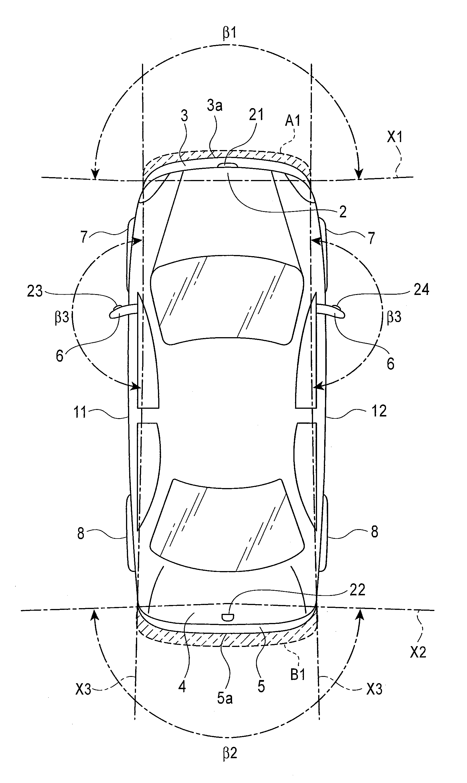
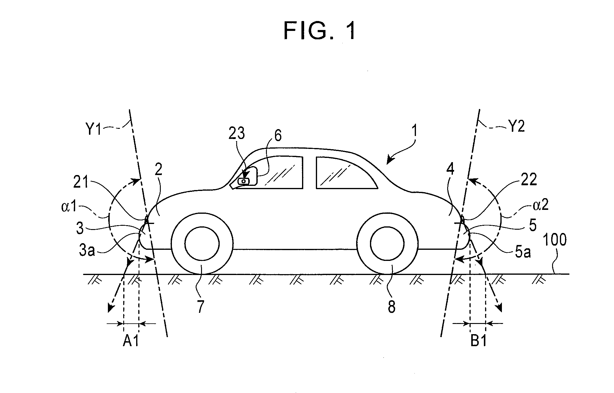
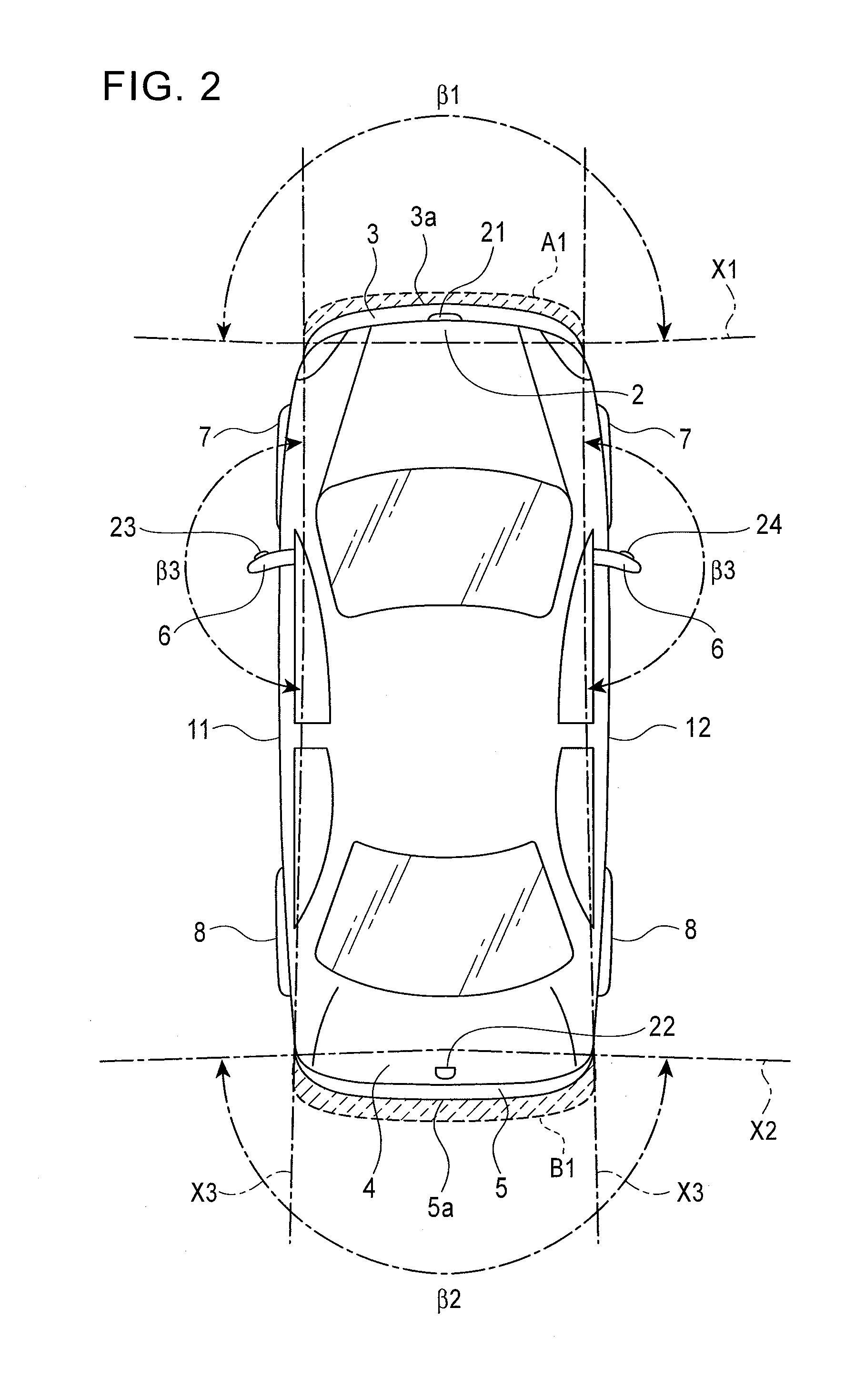
[0038]FIGS. 1 to 3 show a vehicle 1. The diagram of the vehicle 1 shows not an image displayed on the screen of a display device but an actual vehicle.

[0039]The vehicle 1 has a front bumper 3 at a front end 2, and a rear bumper 5 at a rear end 4. Front wheels 7 and 7 and rear wheels 8 and 8 are provided on either side of the vehicle 1. Door mirrors 6 and 6 are provided between the front wheels 7 and 7 and the rear wheels 8 and 8 closer to the front wheels 7 and 7 and toward the upper part of the side of the vehicle 1.

[0040]A front camera 21 is disposed at the front end 2 of the vehicle 1. The front camera 21 is located at the center of the width of the vehicle 1 at the front end 2 of the vehicle 1. As shown in FIGS. 1 and 2, the front camera 21 is located slightly behind a front end 3a of the front bumper 3 which is the forefront end of the vehicle 1. A rear camera 22 is disposed at the rear end 4 of the vehicle 1. The rear camera 22 is located at the center of the width of the vehi...


PUM


Abstract

Images taken by a plurality of cameras mounted on a vehicle are combined and an image of the surrounding area is developed, in a plane, around a vehicle display portion. The vehicle display portion shows an illustration border line indicative of the outer shape of the vehicle. The outline of the vehicle indicated by the illustration border line is drawn slightly larger than the outer shape of the actual image of the vehicle. This allows margin areas to be formed between the vehicle and its surroundings, thus reducing the possibility of a collision with an obstacle during driving.

Description

BACKGROUND OF THE INVENTION[0001]1. Related Applications[0002]The present application claims priority to Japanese Patent Application Number 2007-275483, filed Oct. 23, 2007, the entirety of which is hereby incorporated by reference.[0003]2. Field of the Invention[0004]The present invention relates to on-vehicle image pickup apparatuses for displaying an image composed of images taken by a plurality of cameras provided on a vehicle, and in particular to an on-vehicle image pickup apparatus in which the boundary between the vehicle and its surrounding area can be recognized easily.[0005]3. Description of the Related Art[0006]Japanese Unexamined Patent Application Publication Nos. 3-99952, 8-305999, and 3300334 disclose on-vehicle image pickup apparatuses including a plurality of cameras provided on a vehicle. The cameras each include a lens for focusing images in a wide space area, such as a fisheye lens, and detect the images focused by the lenses with a photo-detector, such as a cha...

Claims


Application Information

Patent Timeline
IPC IPC(8): H04N7/18
CPCB60R2300/102B60R2300/303H04N7/181B60R2300/607B60R2300/806B60R2300/304
Inventor ITO, HARUOABE, KOICHIISHII, HISATOSHI
Owner ALPINE ELECTRONICS INC
Features
  • Generate Ideas
  • Intellectual Property
  • Life Sciences
  • Materials
  • Tech Scout
  • Unparalleled Data Quality
  • Higher Quality Content
  • 60% Fewer Hallucinations
Learn More