Methods and systems for synthesizing pickup images

a pickup image and system technology, applied in the field of image pickup methods and apparatuses, can solve the problems of synthetic images and compressed images not being natural, inability to secure sufficient contrast in the low-level region, and image as a whole will be whitish

Inactive Publication Date: 2010-06-29
SONY CORP
View PDF16 Cites 0 Cited by
  • Summary
  • Abstract
  • Description
  • Claims
  • Application Information

AI Technical Summary

Benefits of technology

[0036]It is further object to overcome the above-mentioned drawbacks of the prior by providing an image processing method adapted to receive a plurality of images sensed in different exposure conditions, respectively, synthesize the input images and compress a synthetic image thus produced, to thereby produce a more natural image.

Problems solved by technology

On the other hand, in the image xS acquired by exposure for the short time, the saturation level is not reached even in the high-level region R1 but no sufficient contrast cannot be secured in the low-level region R2.
As having been described in the foregoing, the conventional image pickup methods including the aforementioned exposure control method, image synthesis method and image compression method are disadvantageous in that synthetic images and compressed images are not natural because a plurality of original images to be synthesized are acquired in different conditions, respectively.
The conventional image pickup methods are also disadvantageous in that since images acquired with larger exposure contain more flare spots, an image produced by synthesis of such sensed images has the level in the dark region thereof relatively increased as caused by the flare spots and thus a resultant image as a whole will be whitish.

Method used


Image

  • Methods and systems for synthesizing pickup images
  • Methods and systems for synthesizing pickup images
  • Methods and systems for synthesizing pickup images

Examples


first embodiment

[0123]Referring now to FIG. 11, there is schematically illustrated in the font of a block diagram the image pickup apparatus according to the present invention. The image pickup apparatus is generally indicated with a reference 10, and it includes an image sensor 11, level compensators 12a and 10b, an image synthesizer 13, and a dynamic range compressor 14.

[0124]Note that input signals to various blocks of the image pickup apparatus 10 are time-series data of pixels acquired by scanning a two-dimensional digital image horizontally and then vertically and a pixel corresponding to a position (i, j) on the image is represented as p (i, j), as shown in FIG. 12.

[0125]The image sensor 11 shown in FIG. 11 has an image sensing device (not shown) such as CCD and an electronic shutter used to control the exposure. Thus, the image sensor 11 outputs a plurality of image signals sensed by exposure for a long time. The image sensor 11 provides as an output a long-time exposure image xL (i, j) sen...

second embodiment

[0146]Next, the image pickup apparatus according to the present invention will be described with reference to FIGS. 16 to 19.

[0147]Referring now to FIG. 16, there is schematically illustrated in the form of a block diagram the second embodiment of the image pickup apparatus according to the present invention. The image pickup apparatus is generally indicated with a reference 20. As shown in FIG. 16, the basic construction of the image pickup apparatus 20 is similar to that of the image pickup apparatus 10 having been described in the foregoing with reference to FIG. 11 except that level compensators 22a and 22b different in construction from each other are provided in place of the level compensators 12a and 12b in the image pickup apparatus 10. Therefore, in FIG. 16, the same and similar elements as those in FIG. 11 are indicated with the same and similar references as those in FIG. 11. Note that also this embodiment will be, described hereinbelow supposing that input signals to var...

third embodiment

[0166]Next, the image pickup apparatus according to the present invention will be described with reference to FIGS. 20 to 22.

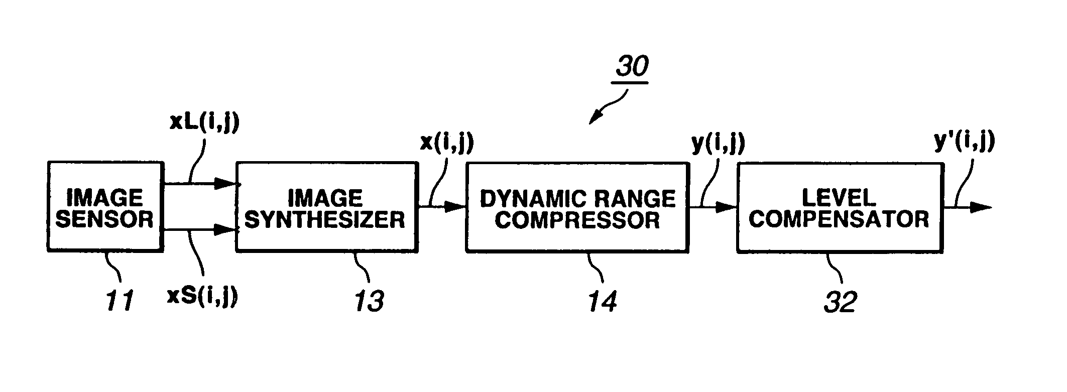
[0167]Referring now to FIG. 20, there is schematically illustrated in the form of a block diagram the third embodiment of the image pickup apparatus according to the present invention. The image pickup apparatus is generally indicated with a reference 30. As shown in FIG. 20, the basic construction of the image pickup apparatus 30 is similar to that of the image pickup apparatus 20 having been described in the foregoing with reference to FIG. 16, except that a single level compensator 32 different in construction from the level compensators 22a and 22b provided upstream of the image synthesizer 13 is provided downstream of the dynamic range compressor 14. Therefore, in FIG. 20, the same and similar elements as those in FIG. 16 are indicated with the same and similar references as those in FIG. 16 and will not further be described. Note that also this embodimen...


PUM


Abstract

In an image pickup apparatus, a level compensator compensates the level of an image xL (i, j) sensed by an image sensor by exposure for a long time on the basis of the exposure of the image to produce a compensated image xL′ (i, j), while another level compensator compensates the level of an image xS (i, j) sensed by the image sensor by exposure for a short time on the basis of the exposure of the image to produce a compensated image xS′ (i, j). The image pickup apparatus also includes an image synthesizer to synthesize these compensates images xL′ (i, j) and xS′ (i, j) to produce a single synthetic image x (i, j). A dynamic range compressor also included in the image pickup apparatus compresses the synthetic image x (i, j) to produce a compressed image y (i, j) for delivery to outside.

Description

CROSS-REFERENCE TO RELATED APPLICATIONS[0001]This is a divisional application of U.S. patent application Ser. No. 09 / 468,053, filed Dec. 20, 1999, the entirety of which is incorporated herein by reference. This application claims the benefits of priority under 35 U.S.C. §119(a)-(d) to Japanese Patent Application No. 10-362899 filed on Dec. 21, 1998 in the Japanese Patent Office.BACKGROUND OF THE INVENTION[0002]1. Field of the Invention[0003]The present invention relates to an image pickup method and apparatus, adapted to synthesize a plurality of images having been acquired by picking up or sensing an object under different exposure conditions, respectively, to produce an image having an excellent gradation reproducibility, and more particularly, to an image pickup method and apparatus suitable for application to a video camera, still camera, monitor camera, on vehicle camera, etc. Also, the present invention relates to an image processing method and apparatus, adapted to receive a ...

Claims


Application Information

Patent Timeline
Patent Type & Authority Patents(United States)
IPC IPC(8): H04N5/235G03B7/00H04N5/335H04N5/353H04N5/355H04N5/378H04N9/04H04N9/64
CPCH04N3/1593H04N5/2353H04N5/35581H04N5/35554H04N5/2355H04N23/741H04N23/73H04N25/41H04N25/583H04N25/589
Inventor OGATA, MASAMITSUCHIYA, TAKASHIUEDA, KAZUHIKO
Owner SONY CORP
Why Eureka
Try Eureka