Computer bag

a computer and carrying case technology, applied in the field of carrying cases, can solve the problems of user's inability to perform computing functions while standing and when mobile, case does not provide any storage means, computer units are stored in the carrying case,

Inactive Publication Date: 2009-04-30
DALEY III CHARLES A
View PDF11 Cites 46 Cited by
  • Summary
  • Abstract
  • Description
  • Claims
  • Application Information

AI Technical Summary

Problems solved by technology

However, the problem is that the carrying case is designed so that the user can only use the computer on a user's lap while the computer is in contact with the carrying case.
A user cannot perform computing functions while standing and when mobile.
The problem here is that the structure of the carrying case is strictly designed to carry only the portable computer.
The case does not provide any storage means should the user desire to carry additional peripherals.
However, the disadvantage is that the computer unit is stored within the carrying case and must first be unpacked before it is used.
Further, besides the utility flaps and pockets, the carrying case does not provide general storage for other computer peripherals.
The problem here is similar to other apparatuses such that the protective carrying bag is strictly designed to carry only the portable computer.
The case does not provide any additional storage room for the user to carry additional peripherals.
While the carrying case provides a means to pass wiring connections to a computer through adjustable windows in the case, the computer drive case does not provide housing for a computer unit.
While these prior computer bags are mainly for use with a laptop computing device which protects the device during transport as well as provides a work platform for a portable computer, these bags do not provide additional storage compartments for computer peripherals.
Additionally, many prior carrying cases have the portable computers enclosed within the carrying case and require unpacking and set-up of the computer before use.
However, these carrying cases do not provide extra storage for carrying additional computer components, accessories or peripherals.

Method used


Image

  • Computer bag
  • Computer bag
  • Computer bag

Examples


Embodiment Construction

[0037]The description above and below and the drawings of the present document focus on one or more preferred embodiments of the present invention and also describe some exemplary optional features and / or alternative embodiments. The description and drawings are for the purpose of illustration and not limitation. Those of ordinary skill in the art will recognize variations, modifications, and alternatives. Such variations, modifications, and alternatives are also within the scope of the present invention. Section titles are terse and are for convenience only.

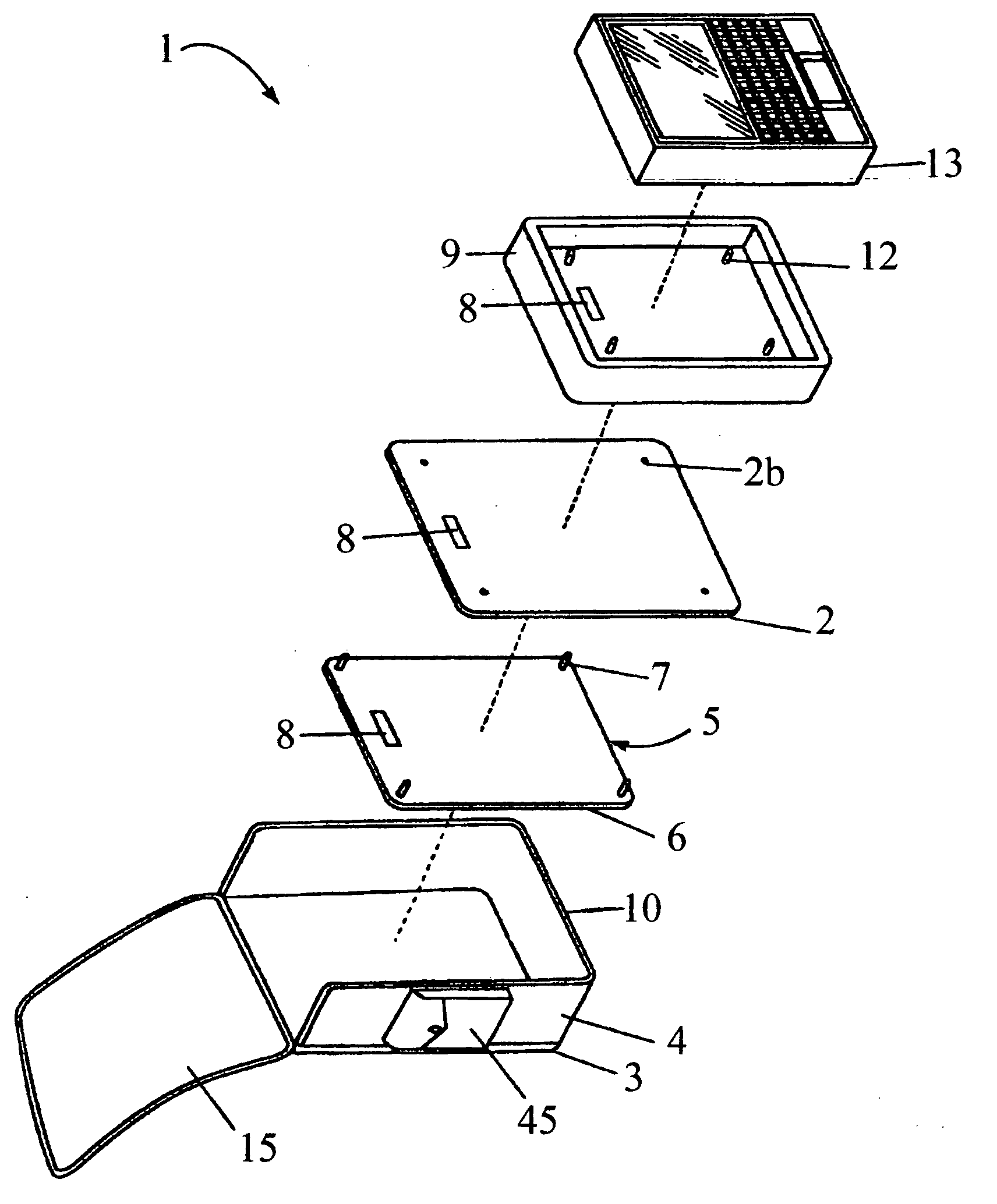
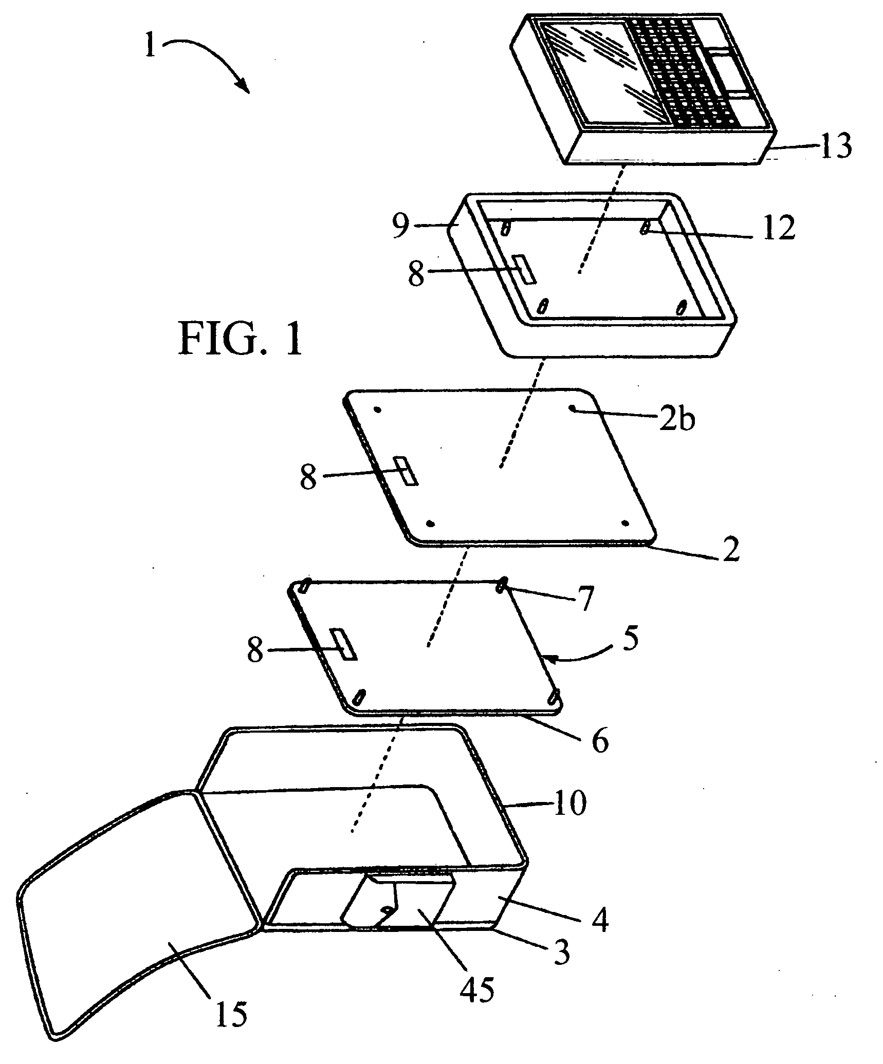
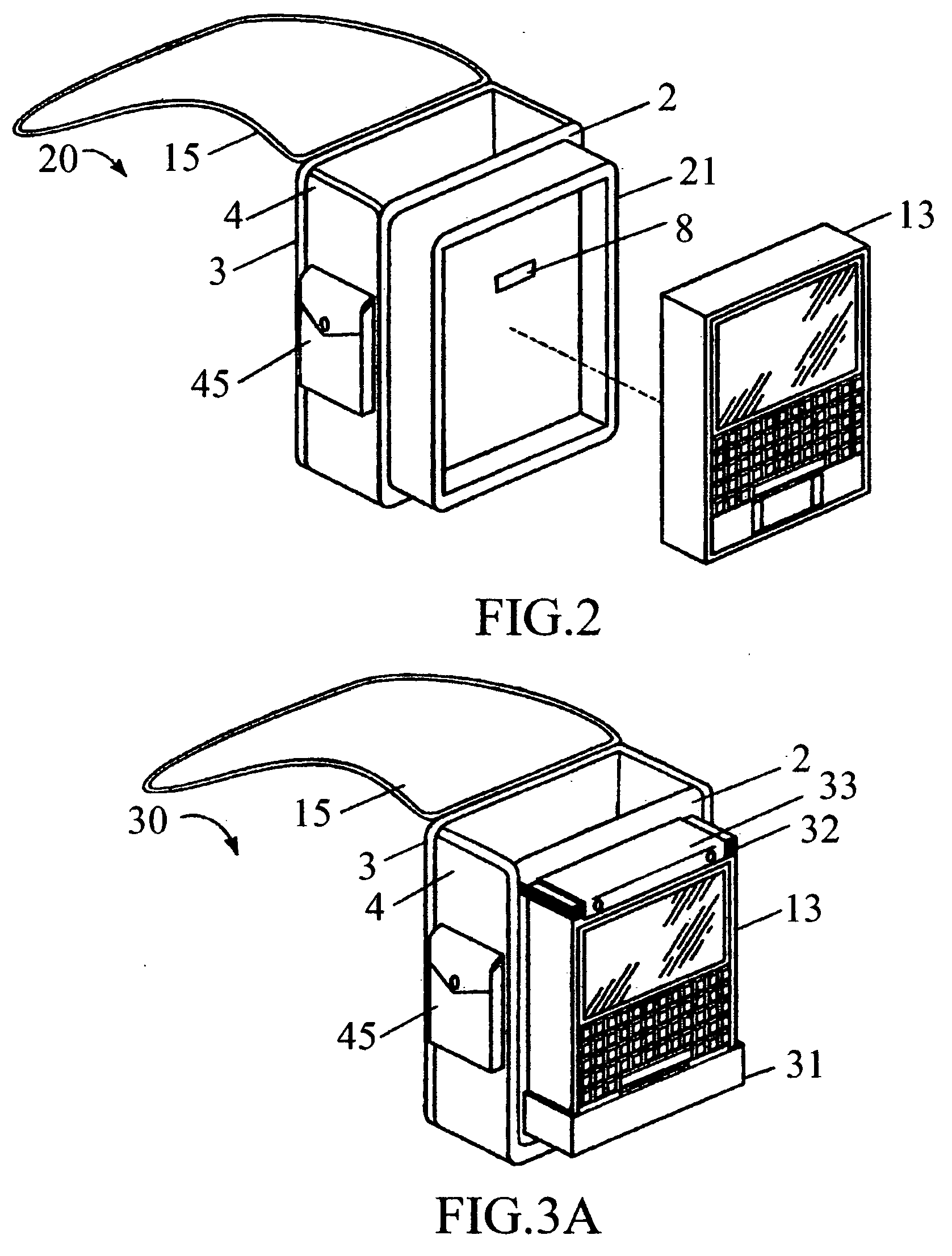
[0038]An embodiment of the present invention includes a computer bag apparatus as shown in FIG. 1. Bag 1 has a front wall 2, an opposing back wall 3, a bottom wall 10, and side walls 4 connecting the front wall to the back wall. Bag 1 has a front wall 2, an opposing back wall 3, a bottom wall 10, and a plurality of side walls 4, bottom wall 10 and side walls 4 connect the front wall 2 to the back wall 3. Each wall has an inside ...


PUM

PropertyMeasurementUnit
structureaaaaaaaaaa
flexibleaaaaaaaaaa
elasticaaaaaaaaaa

Abstract

A bag apparatus for carrying a portable computer where the computer is mounted to an outside surface of the bag for quick and convenient access where a user can perform computing tasks ergonomically with the hands and eyes in their normal positions. The bag includes a means for providing electrical connections to access the interior surface of the bag. The bag further provides extra storage for carrying additional computer components, accessories or peripherals.

Description

CROSS-REFERENCE TO RELATED APPLICATIONS[0001]This application is a divisional application from U.S. application Ser. No. 11 / 001,428, filed Nov. 30, 2004.TECHNICAL FIELD[0002]The present invention relates to a carrying case for a computer and peripherals.BACKGROUND OF THE INVENTION[0003]Most computer bags are made for a lap top with the primary purpose of carrying them from desk to desk in safety. Further, most carrying cases for portable computers enclose the computer within the case. Some carrying cases are adapted for use as both a carrying case for a computer and as a work platform for the computer. One apparatus has been described as an article of luggage or a carrying case which protects the laptop computing device during periods of non-use, including transport and further provides a means for stabilizing the computing device on one's lap during use. The carrying case remains in contact with the computing device during use of the computer when positioned on a user's lap. Howeve...

Claims


Application Information

Patent Timeline
Patent Type & Authority Applications(United States)
IPC IPC(8): B65D69/00B65D85/00
CPCA45C5/02G06F1/1628A45C2013/025
Inventor DALEY, III, CHARLES A.
Owner DALEY III CHARLES A
Why Eureka
Try Eureka