
Hair styling iron with retractable fins

a technology of hair styling iron and retractable fin, which is applied in the direction of curling iron, curling-tong, hair equipment, etc., can solve the problems of poor heat conductivity, poor heat transfer effect, and inability to provide optimal performance for simultaneously straightening hair, so as to achieve optimum heat transfer, straighten hair, and detangling

Active Publication Date: 2009-05-07
CONAIR CORP
View PDF8 Cites 36 Cited by
  • Summary
  • Abstract
  • Description
  • Claims
  • Application Information

AI Technical Summary

Benefits of technology

[0004]It is an object of the present invention to provide a heated styling iron that achieves straightening, detangling, and optimum heat transfer in a manner that overcomes the shortcomings described above. It is another object of the present invention to provide a heated styling iron that is versatile and that can be configured into a plurality of modes for different styling functions.
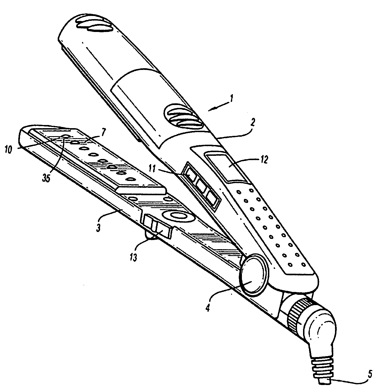
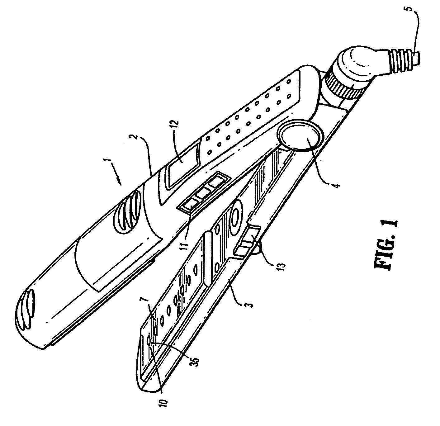
[0006]According to the present invention, a heated styling iron having two opposed heated surfaces attached to respective members that are hingedly connected to each other achieves straightening, detangling and optimum heat transfer by utilizing on one flat heated surface a row of fin-like raised ridges that are spaced apart longitudinally in a single row and that are oriented so that the longer dimension of the fin-like ridges are aligned generally transversely to the longitudinal axis. Thus, as the iron is pulled through the hair the ridges guide the hair along their longer dimension. The opposing flat heated surface has a channel or groove that extends longitudinally in a manner so that it complementarily receives the row of ridges when the heated surfaces are closed against each other. The sizing and shape of the groove is optimized to receive the ridges while the heated surfaces are closing around a lock of hair. In another aspect of the invention, the raised ridges may be retractably mounted in order to be selectively retracted into or extended from the flat heated surface. The fins may be received into openings in the surface. The fins may be fixed at one or more heights for selective styling preferences. The fins may also be retracted fully to present a flush, smooth heated surface. Alternatively, the opposite flat heated surface may be formed without a channel or groove and the fins may be spring-biased so that, while initially raised, the fins will retract against the spring and flatten when pressed against the opposite surface. In another aspect of the present invention, a water reservoir and steam generator may be included with means for selectively controlling variable steam output level.

Problems solved by technology

While each has a specialized purpose, such as shaping hair in a particular way, or detangling hair, none provide optimal performance for simultaneously straightening hair, detangling hair, and delivering optimum heat transfer.
For example, designs that have mere pins or bristle-like protrusions effectively comb through hair, and in some instances detangle the hair, yet the pins are poor heat conductors and, therefore, do little to transfer heat.
The result is that the heat transfer is almost entirely limited to surfaces of the flat iron that directly contact the hair.
Furthermore, pins, particularly if a relatively large number are employed, have a tendency to get stuck in tangled hair and are difficult to pull through, particularly without causing discomfort.

Method used


Image

  • Hair styling iron with retractable fins
  • Hair styling iron with retractable fins
  • Hair styling iron with retractable fins

Examples


Embodiment Construction

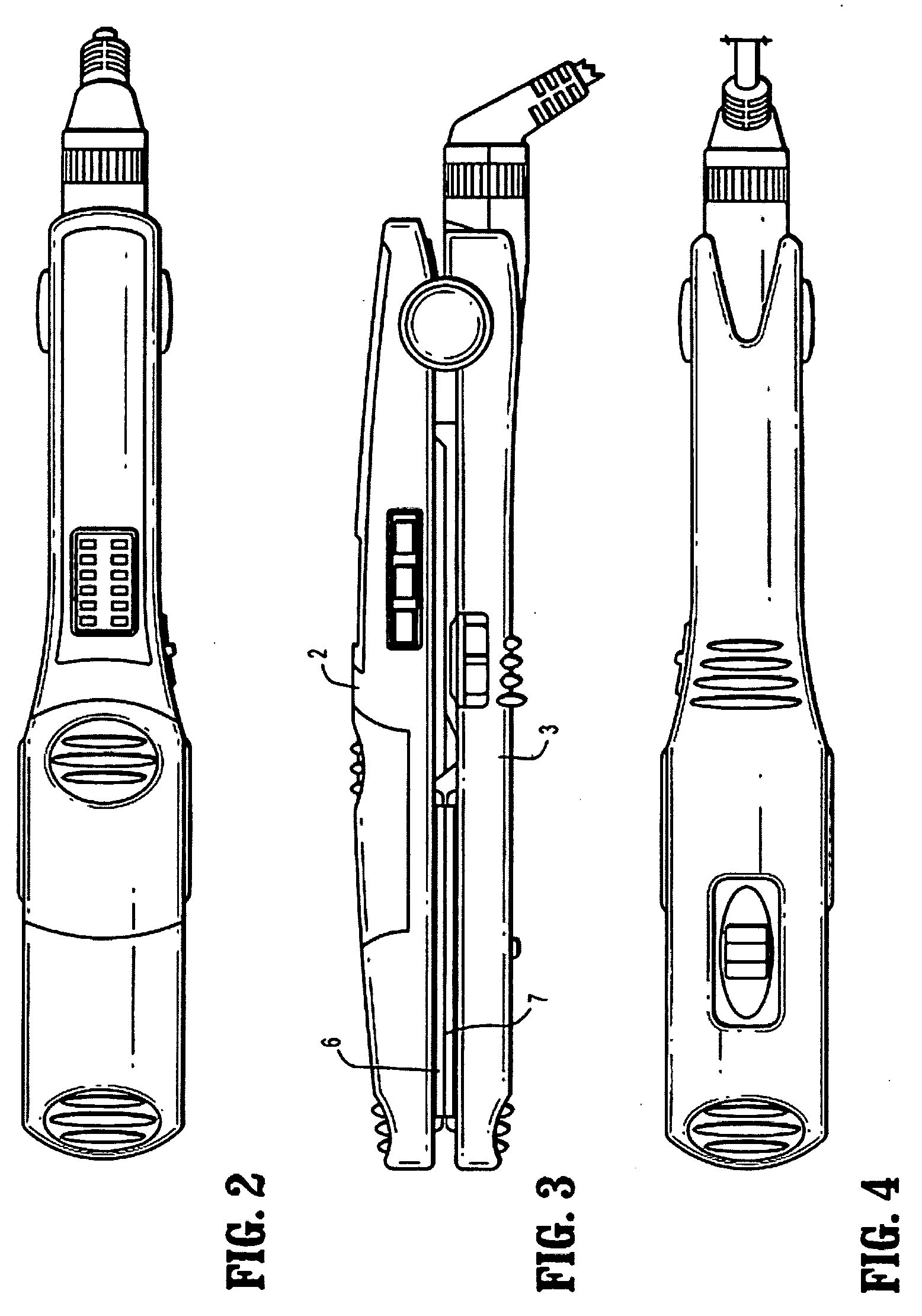
[0008]Referring to the drawing figures, a heated flat iron 1 includes a first elongated member 2 and a second elongated member 3 that are joined together at one end at a hinge 4. An electrical cord 5 is attached thereto and has a conventional plug (not shown) to connect the iron 1 to a conventional external electrical energy source. An upper plate 6 is attached to the first member 2, and a lower plate 7 us attached to the second member 3. The upper plate 6 comprises a longitudinally aligned groove 8, preferably including in the groove 8 a series of longitudinally spaced laterally oriented slot depressions 9. The lower plate 7 includes a set of raised ridges 10, each having a length L that is transverse to the longitudinal axis of the second member 3, a height H measured in a direction extending away from the surface of the lower plate 7, and a thickness T measured transversely to length L, where L is greater than T. The ridges 10 are aligned in a longitudinally extending row along t...


PUM


Abstract

A heated flat iron 1 includes a first elongated member 2 and a second elongated member 3 that are joined together at one end at a hinge 4. An electrical cord 5 is attached thereto and has a conventional plug (not shown) to connect the iron 1 to a conventional external electrical energy source. An upper plate 6 is attached to the first member 2, and a lower plate 7 us attached to the second member 3. The upper plate 6 comprises a longitudinally aligned groove 8, preferably including in the groove 8 a series of longitudinally spaced laterally oriented slot depressions 9. The lower plate 7 includes a set of raised ridges 10, each having a length L that is transverse to the longitudinal axis of the second member 3, a height H measured in a direction extending away from the surface of the lower plate 7, and a thickness T measured transversely to length L, where L is greater than T. The ridges 10 are aligned in a longitudinally extending row along the lower plate 7 so that the row is aligned with the groove 8 and each ridge 10 corresponds in alignment with one of the slot depressions 9. The height of the ridges 10 may be adjustably varied.

Description

CROSS-REFERENCE TO RELATED APPLICATIONS[0001]This application relates to and claims priority from U.S. Provisional Application No. 60 / 997,583 filed 4 Oct. 2007.BACKGROUND OF THE INVENTION[0002]The present invention relates to hair care appliances and, more particularly, to hair styling devices having heated plates.DESCRIPTION OF RELATED ART[0003]Various known hair styling irons have heated, flat plates. Certain flat irons have non-flat heated surfaces comprising one or more of raised contours, grooves, pins and channels. While each has a specialized purpose, such as shaping hair in a particular way, or detangling hair, none provide optimal performance for simultaneously straightening hair, detangling hair, and delivering optimum heat transfer. For example, designs that have mere pins or bristle-like protrusions effectively comb through hair, and in some instances detangle the hair, yet the pins are poor heat conductors and, therefore, do little to transfer heat. The result is that t...

Claims


Application Information

Patent Timeline
Patent Type & Authority Applications(United States)
IPC IPC(8): A45D1/00A45D1/04
CPCA45D1/06A45D1/04
Inventor LEUNG, ANTHONY KIT LUN
Owner CONAIR CORP
Learn More