Boundary acoustic wave device

a technology of boundary acoustic waves and acoustic waves, which is applied in piezoelectric/electrostrictive/magnetostrictive devices, piezoelectric/electrostriction/magnetostriction machines, etc., can solve the problems of difficult reduction in size of boundary acoustic wave devices, insufficient trapping efficiency of vibrational energy, and increase in thickness of first and second media, so as to efficiently trap the vibrational energy of boundary

Active Publication Date: 2009-05-07
MURATA MFG CO LTD
View PDF10 Cites 51 Cited by
  • Summary
  • Abstract
  • Description
  • Claims
  • Application Information

AI Technical Summary

Benefits of technology

[0017]In order to overcome the problems described above, preferred embodiments of the present invention provide a boundary acoustic wave device that has a multilayer structure including a first medium, a third medium and a second medium stacked in that order, that can efficiently trap the vibrational energy of boundary acoustic waves in the third medium so as to exhibit a low boundary acoustic wave propagation loss and a high electromechanical coupling coefficient so as not to be affected by higher-order modes that produce undesired spurious responses, and thus can produce superior resonance characteristics or filter properties, and that is not easily cracked in the third medium.

Problems solved by technology

Accordingly, the trapping efficiency of the vibrational energy is not satisfactory, and the thicknesses of the first and second media are increased.
It has been thus considered that boundary acoustic wave devices are difficult to reduce in size.
Accordingly, the reflectors are inevitably large, and the resulting boundary acoustic wave device therefore must be large.
If the third medium is formed by deposition, such as sputtering, it is difficult to increase the thickness of the third medium to a sufficiently larger value than the thickness of the strips of the IDT and reflectors.
A third medium having a small thickness may be cracked due to the unevenness between regions having the strips and regions having no strips.

Method used


Image

  • Boundary acoustic wave device
  • Boundary acoustic wave device
  • Boundary acoustic wave device

Examples


Embodiment Construction

[0093]The present invention will become clear from the description of specific preferred embodiments of the present invention with reference to the drawings.

[0094]In the Description, the Euler angles, the crystallographic axis, and equivalent Euler angles refer to the following.

Euler Angles

[0095]In the Description, the Euler angles (φ, θ, ψ) representing the direction of the cut surface of the substrate and the propagation direction of the boundary waves are based on the right-handed Euler angles described in a document “Danseiha Soshi Gijutsu Handbook (Acoustic Wave Device Technology Handbook)” (Japan Society for the Promotion of Science, Acoustic Wave Device Technology the 150th Committee, 1st Version 1st printing, published on Jan. 30, 2001, p. 549). Specifically, in LN crystallographic axes X, Y, and Z, the X axis is rotated φ turn counterclockwise about the Z axis to define a Xa axis. Subsequently, the Z axis is rotated θ turn counterclockwise about the Xa axis to define a Z′ a...


PUM


Abstract

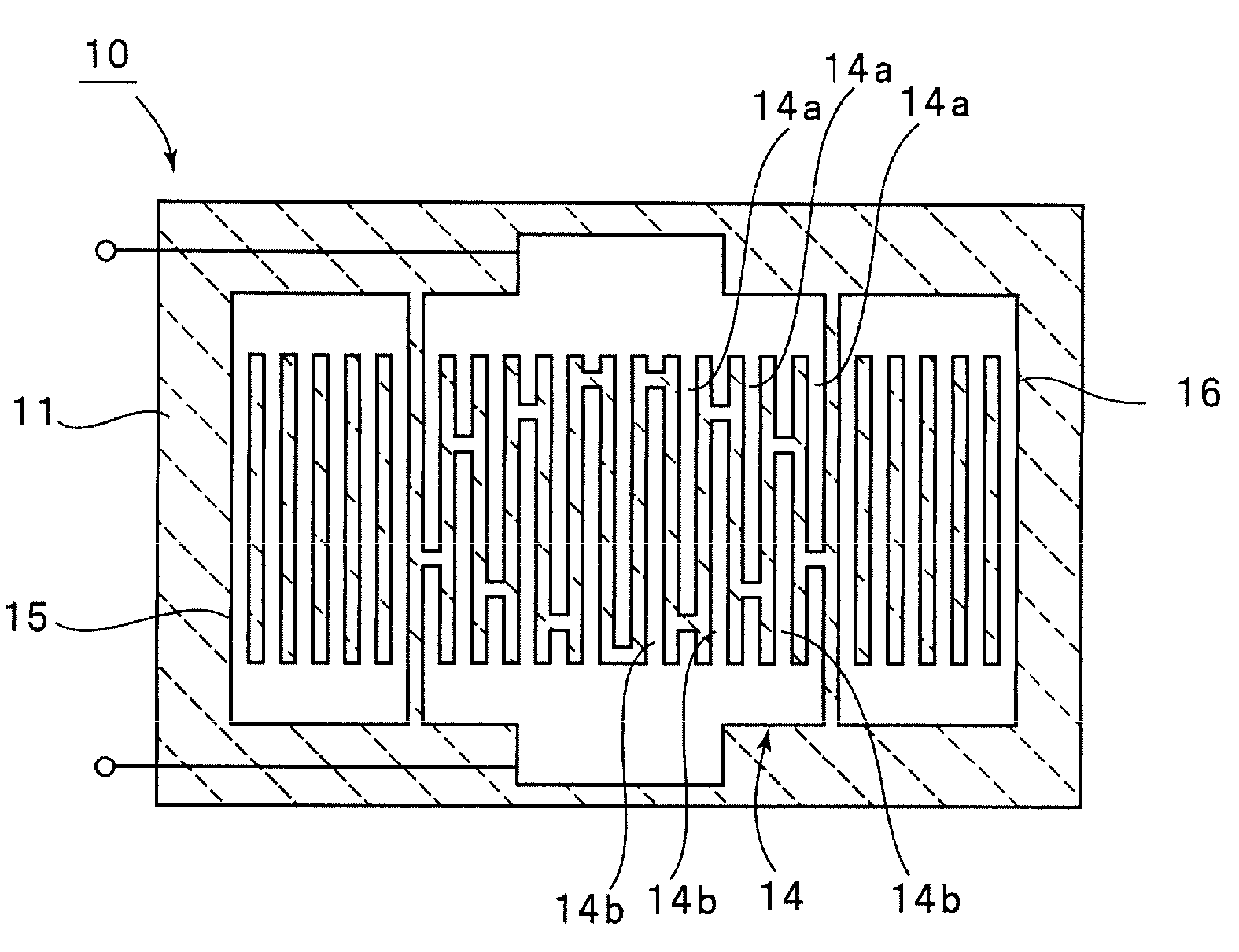
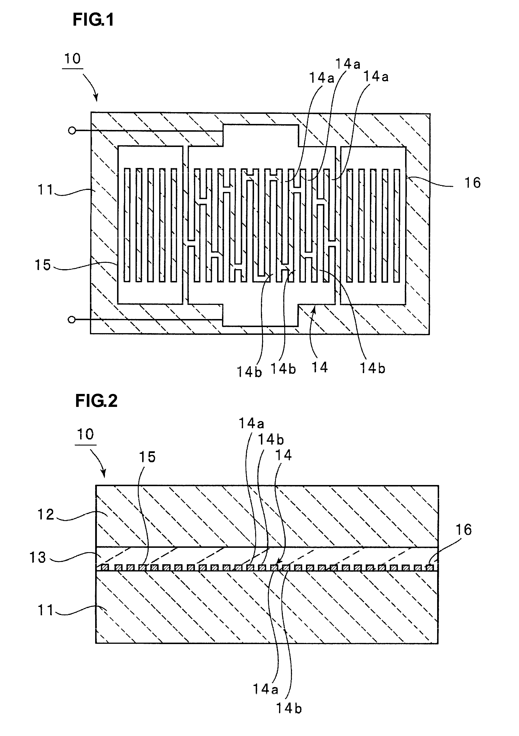
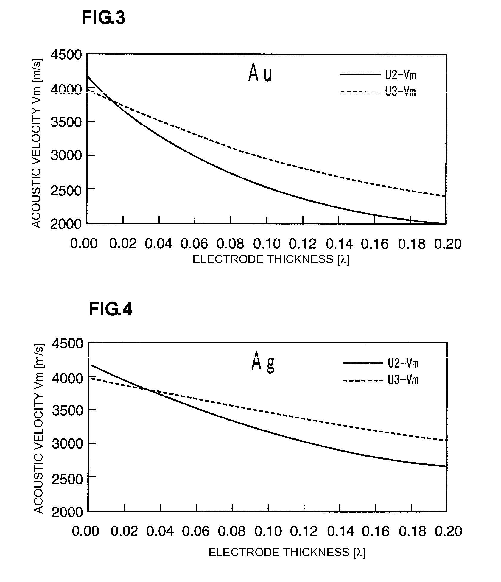
A boundary acoustic wave device efficiently traps the vibrational energy of boundary acoustic waves and exhibits a high electromechanical coupling coefficient, and is consequently not affected by higher-order modes. The boundary acoustic wave device includes a first medium having piezoelectric characteristics, a non-electroconductive second medium, and a third medium through which slow transverse waves propagate at a lower acoustic velocity than slow transverse waves propagating through the first and second media. The first medium, the third medium, and the second medium are stacked in that order. An IDT is disposed between the first medium and the third medium. The IDT includes a metal layer made of a metal having a density ρ in the range of about 3000 kg/m3 to about 21500 kg/m3. The IDT has electrode fingers arranged at a pitch of λ and has a thickness H1 satisfying the relationship 0.006λ≦H1≦0.2λ, and the third medium has a thickness H2 satisfying the relationship H1<H2≦0.7λ.

Description

BACKGROUND OF THE INVENTION[0001]1. Field of the Invention[0002]The present invention relates to boundary acoustic wave devices using boundary acoustic waves propagating along an interface between different media, and more particularly, to a boundary acoustic wave device including a multilayer structure formed by stacking at least three media.[0003]2. Description of the Related Art[0004]A variety of devices using boundary acoustic waves, such as resonators and band-pass filters, have been proposed. Boundary acoustic waves propagate along the interface between different media. Therefore, the packages of boundary acoustic wave devices can be simpler than those of surface acoustic wave devices using surface acoustic waves. The boundary acoustic wave device thus can be more simplified, and have reduced thickness.[0005]A non-patent literature document (Toshio IRINO, et al., “Propagation Boundary Acoustic Waves Along a ZnO Layer Between Two Materials”, IEICE Material, Vol. 86, No. 177, US...

Claims


Application Information

Patent Timeline
Patent Type & Authority Applications(United States)
IPC IPC(8): H03H9/64
CPCH03H9/0222H03H9/14538H03H9/02559
Inventor KANDO, HAJIME
Owner MURATA MFG CO LTD
Why Eureka
Try Eureka