

Flying wing boat
- Summary
- Abstract
- Description
- Claims
- Application Information
AI Technical Summary
Benefits of technology
Problems solved by technology
Method used
Image

Examples
first embodiment
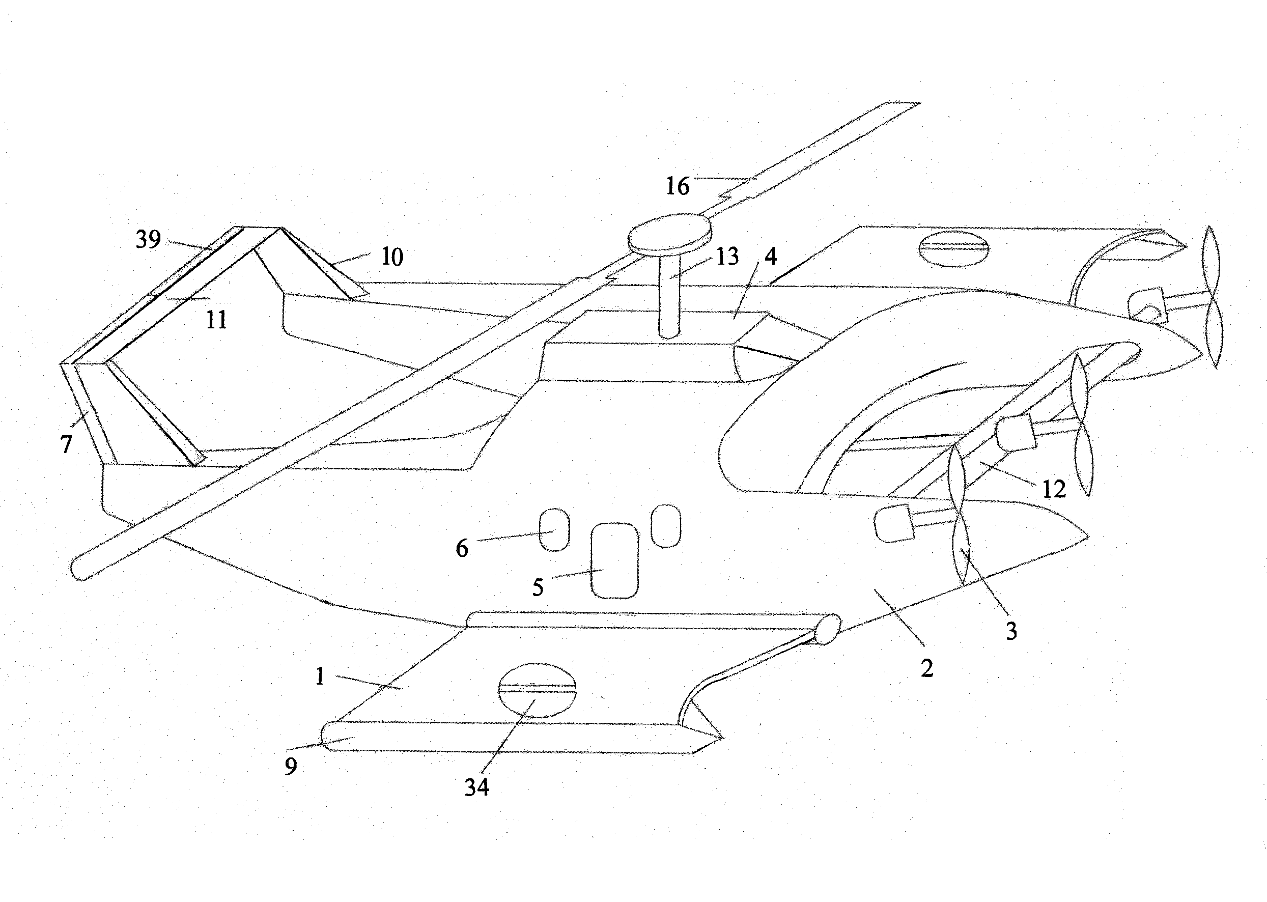
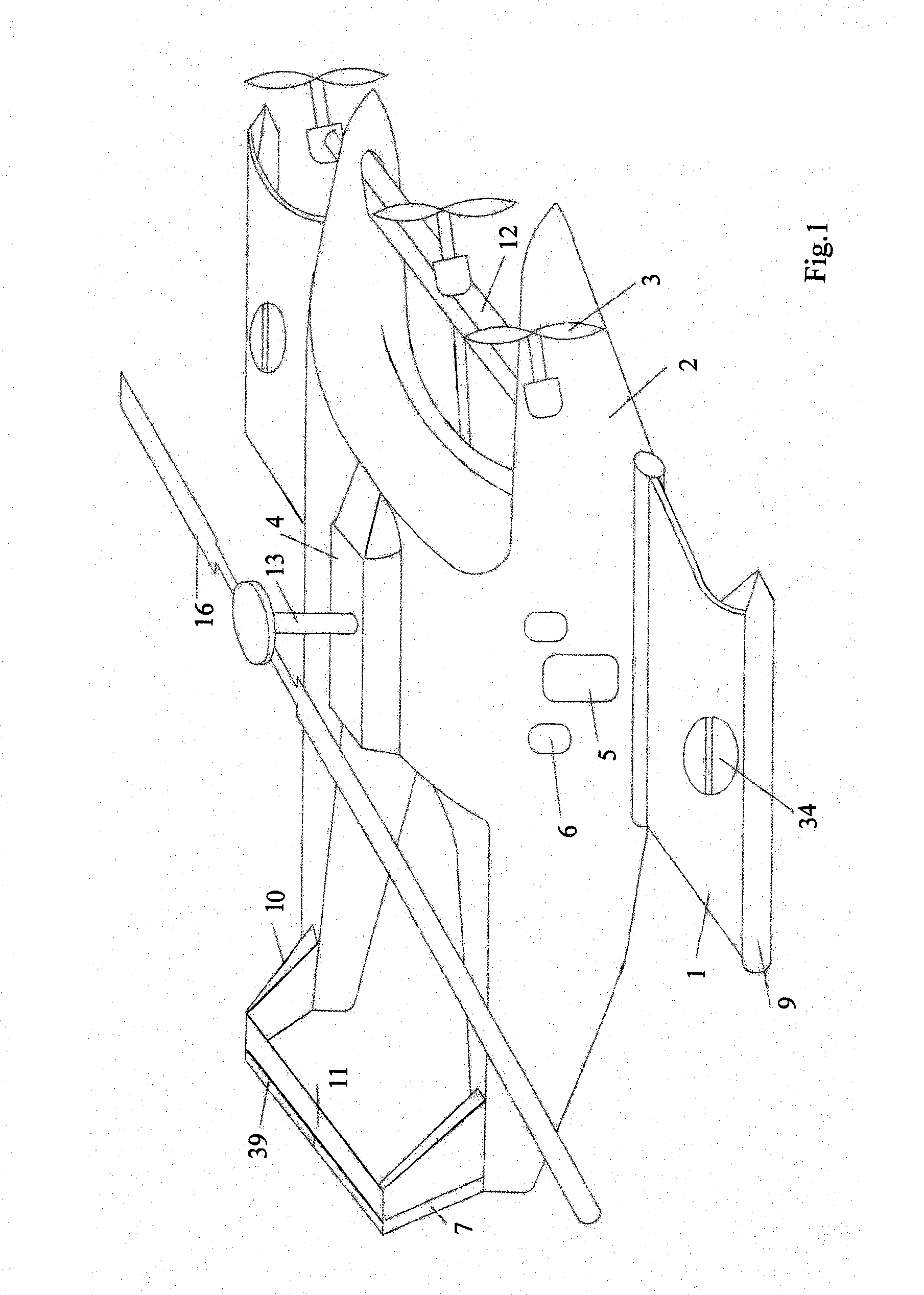
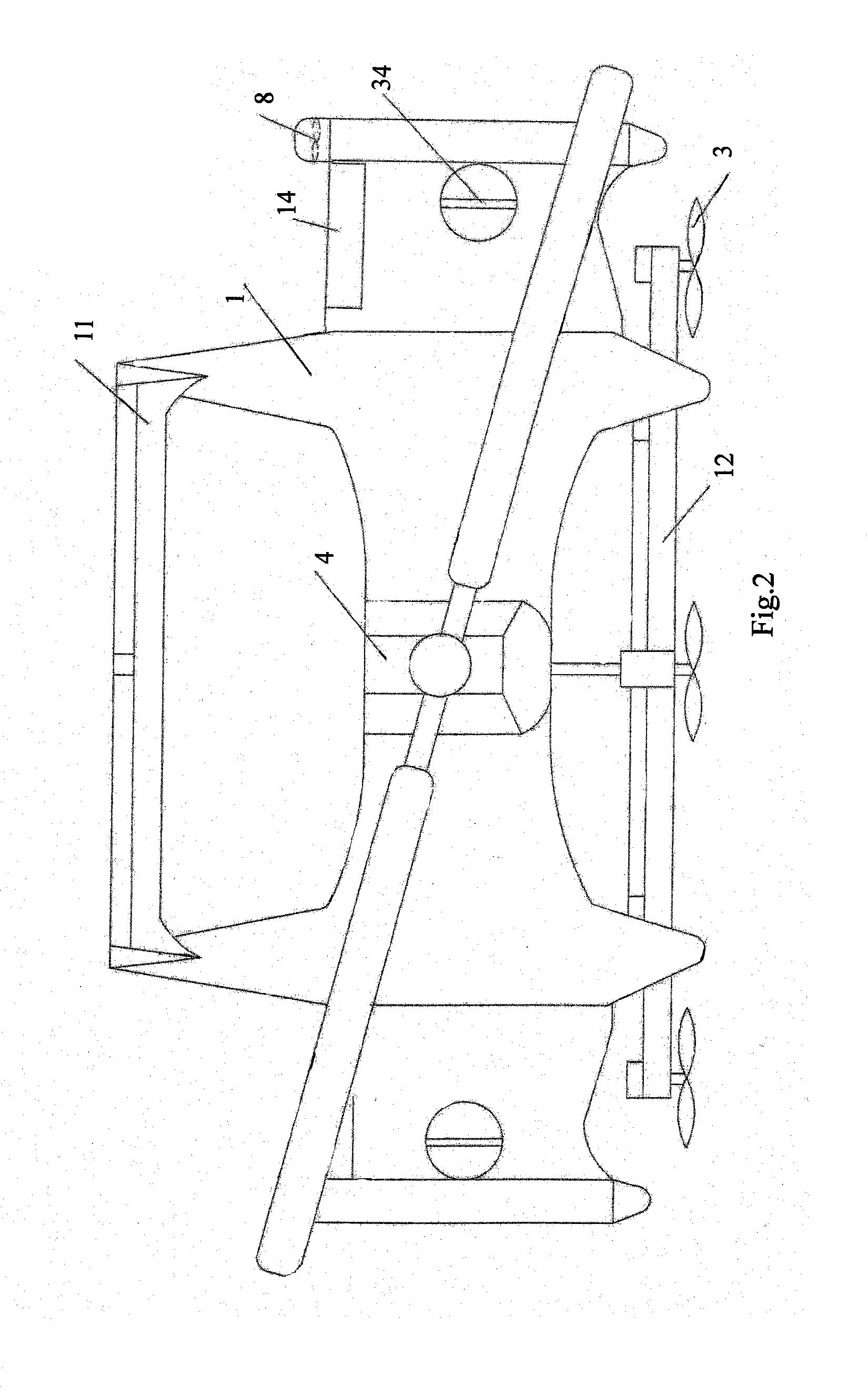
[0029]FIGS. 1-12, 14A and 14B show the flying wing boat of the present invention. In the embodiment, the flying wing boat comprises a fuselage 2, a pair of main wings 1 provided with a flap 14 at the trailing edge 62 of each main wing, a pair of pontoon 9; a tail wing, and a driving system. The fuselage 2 is designed to connect to the main wings 1 to form a flying wing contour, which contour is in an “H” shape viewed from above and in an arch shape viewed from ahead. Upon viewed from side, the contour is in streamline. A cockpit 4 is provided at the top the fuselage 2, and doors 5 and scuttles 6 are provided at both sides of the fuselage 2. A rotary shaft 13 is mounted on the cockpit 4, and a rotary wing 16 is fixed on the tip of the rotary shaft 13. A pair of vertical tail wings 10 and a horizontal tail wing 11 are provided at the aft part of the fuselage 2, in which the vertical tail wings 10 connect to the fuselage 2 and the horizontal tail wing 11 bridges at the tip of the verti...
second embodiment
[0044]FIG. 15 illustrates the fluid conducting means of the present invention.
[0045]As shown in FIG. 15, the second embodiment of the fluid conducting means is also provided at the middle part of each main wing 1, just like the first embodiment. Each fluid conducting means 34′ of the second embodiment comprises: a gear wheel 40, which includes an inner ring 19 fixedly mounted on the main wing 1 and an outer ring 43 provided with a plurality of teeth on the outer surface thereof and rotatable with respect to the inner ring 19, in which there is a through hole provided in the main wing 1 to correspond to the through hole at the center of the inner ring 19; a middle shaft 33 bridging the inner ring 19 and revolvably mounted on the outer ring 43 at both ends thereof along the diameter of the gear wheel 40; a third motor 35 mounted on the outer ring 43 and connecting to one of the ends of the middle shaft 33 to make the middle shaft 33 revolve about the longitudinal axis of itself; a thi...
PUM
 Abstract
Description
Claims
Application Information