Harvesting corn cobs

a corn cob and harvesting technology, applied in biofuels, solid separation, agriculture tools and machines, etc., can solve the problems of crude cob collection methods, no commercially available equipment to collect corn cobs, and insufficient cleaning methods to properly collect all

Inactive Publication Date: 2009-05-14
REDEKOP ENTERPRISES
View PDF23 Cites 55 Cited by
  • Summary
  • Abstract
  • Description
  • Claims
  • Application Information

AI Technical Summary

Benefits of technology

[0042]Preferably there is provided a hood for receiving the air from the stages and wherein the hood is sh...

Problems solved by technology

There is currently no commercially available equipment to collect corn cobs and a very small number of people that have built equipment to collect cobs themselves.
Current methods to collect cobs are very crude.
Problems with existing technology:
Cleaning methods are not sophisticated enough to properly collect all cobs so ...

Method used


Image

  • Harvesting corn cobs
  • Harvesting corn cobs
  • Harvesting corn cobs

Examples


first embodiment

[0132]The following description of further embodiments of the invention discloses elements and features which may also be used in the first embodiment described above.

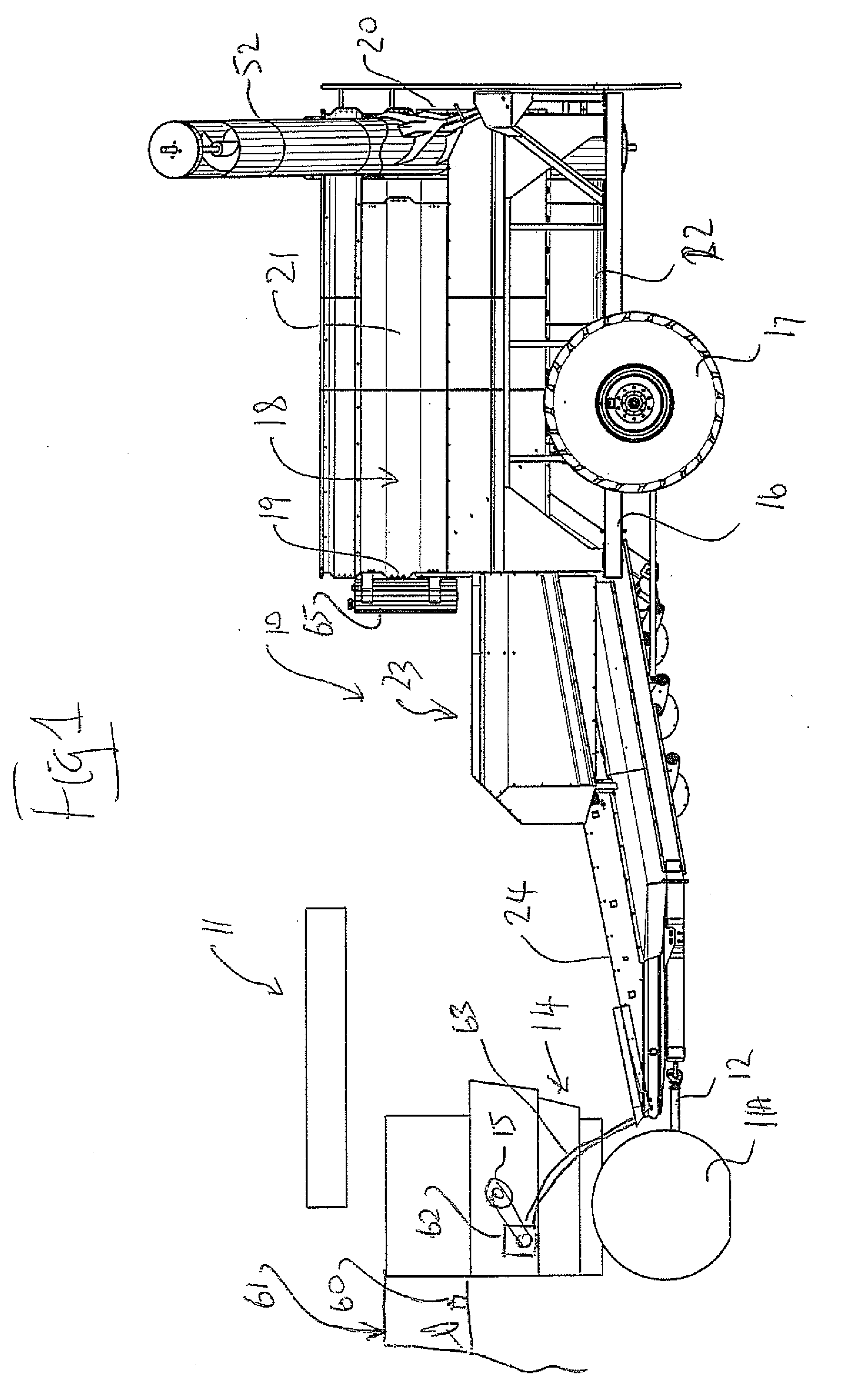
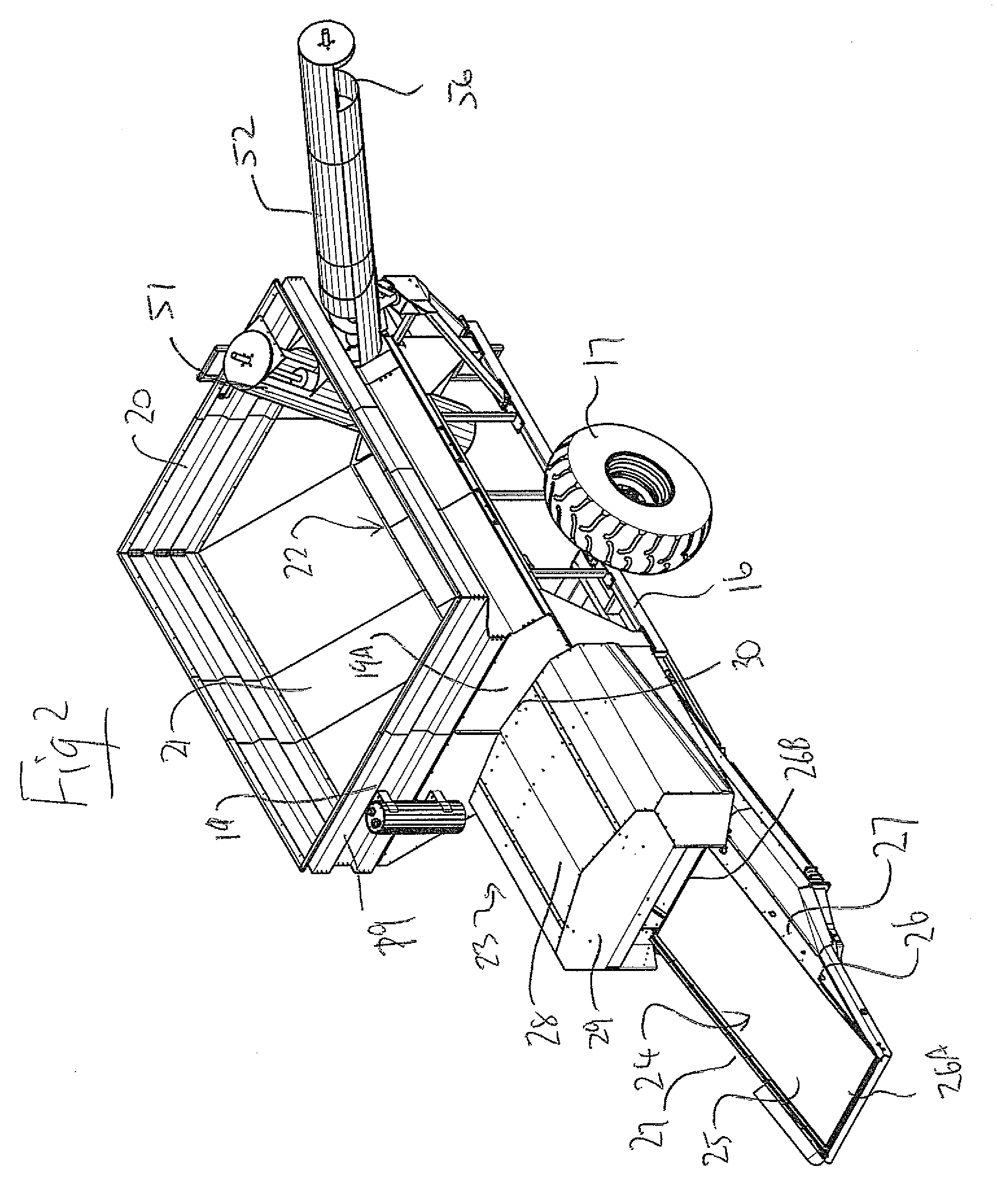
[0133]Referring to FIGS. 14 and 15, a corn cob harvesting machine 110 is pulled behind the rear end of a typical combine 111. The combine 111 is equipped with a specialized hitch 112 to quickly disconnect the cob harvesting machine, as it is a common practice to switch between harvesting corn and soybean on a daily basis dependant on the weather. The cob harvester is powered hydraulically by a drive system 113 taking power from combine's chopper drive.

[0134]The corn cob harvester includes an inlet conveyor 120 that has a feed hopper 121 placed under the combine's residue outlet 114. It is preferable that the residue from the sieves 115 as well as the walkers or rotors 116 (depending on combine type) be combined in the inlet conveyor's hopper to capture all possible cobs.

[0135]The inlet conveyor 120 elevates the residue...

third embodiment

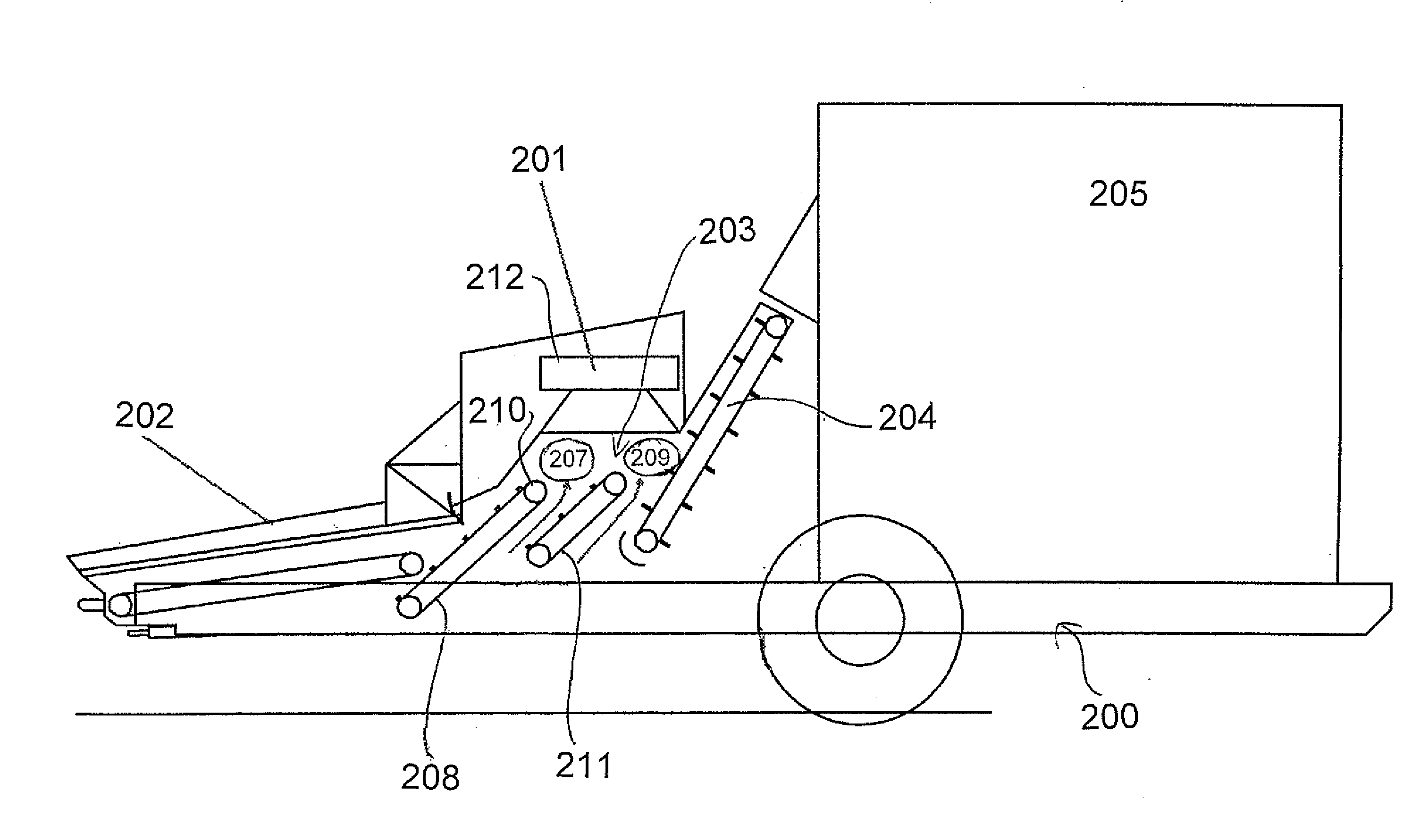
[0145]Referring now to the third embodiment shown in FIG. 21, a corncob harvesting machine 210 of the same general type as that disclosed above is pulled behind the rear end of the combine 211. The combine is equipped with a specialized hitch 212 of the arrangement previously described to quickly disconnect the cob harvesting machine. The cob harvester is powered hydraulically by a drive system (not shown) taking a drive outlet from the combine's chopper drive, again as previously described.

[0146]The corn cob harvester includes the inlet conveyor 220 that has its feed hopper 221 placed under the combine's residue outlet 214. It is preferable that the residue from the sieves as well as the walkers or rotors (depending on combine type) be collected in the inlet conveyor's hopper in order to capture all possible cobs.

[0147]The inlet conveyor elevates the residue and drops the stover into a cob separating region 280. The cob separating mechanism includes a fan 281 for generating air jet...

fourth embodiment

[0154]Referring now to the fourth embodiment shown in FIGS. 24 to 27, this uses the same trailer construction and using many of the features described above.


PUM


Abstract

A cart is towed behind a combine harvester for collecting corn cobs and includes a conveyer belt feeding into a system for separating cobs from residue to be discharged and a tank for receiving and transporting the cobs. An unload auger is provided from the tank to one side of the cart while the cart moves forward. Power for driving the cart is obtained from a chopper drive of the combine harvester. The separating arrangement includes a suction fan or a single blower fan or a series of blower fans for blowing air through material from a conveyor and into a spreading guide which disperses the residue. The cobs are conveyed using a series of augers where the auger to flight distance is at least 2 inches and particularly a pair of augers feed the cobs through a front wall of the tank so as to push cobs upwardly into the tank.

Description

[0001]This application claims the benefit under 35 U.S.C. 119 of Provisional Applications Nos. 60 / 986,438 filed Nov. 8, 2007 and 61 / 087,409 filed Aug. 8, 2008, the disclosures of which are incorporated herein by reference.[0002]This invention relates to agricultural harvesting machines and including a device to separate the corn cobs from the residue discharged from a combine when harvesting corn. The arrangement described and claimed herein can be towed behind a combine harvester to directly receive the material from the combine harvester or may be towed separately after the combining action is complete and includes a pick-up at the front of the inlet conveyor in order to pick up the material from the ground.BACKGROUND OF THE INVENTION[0003]World ethanol production is expected to experience double-digit growth in the next years. Much of the growth is expected to occur in the United States where, with the current pace of expansion, the United States will be the leading producer of e...

Claims


Application Information

Patent Timeline
IPC IPC(8): A01F12/44
CPCA01D45/02Y02E50/10
Inventor REDEKOP, LEOMAYERLE, DEAN
Owner REDEKOP ENTERPRISES
Why Eureka
Try Eureka