Apparatus for chopping and discharging straw from a combine harvester

a combine harvester and chopping technology, applied in the field of chopping and discharging straw from combine harvesters, can solve the problems of increasing construction costs, requiring relatively wide spacing between stationary blades, and not achieving significant commercial success in arrangement, so as to prevent direct feeding of crop material, shorten cutting length, and increase air flow

Inactive Publication Date: 2005-01-11
TRITANA HLDG LTD
View PDF20 Cites 49 Cited by
  • Summary
  • Abstract
  • Description
  • Claims
  • Application Information

AI Technical Summary

Benefits of technology

Preferably the fan blade members in each of the fan sections are arranged such that the velocity of air exiting radially from the discharge opening at the respective fan section is greater than 75 ft / s and preferably of the order of 125 ft / s. Of course the air exiting the center section is at much lower velocity, and at the center it can be as low as 30 ft / s. However surprisingly it has been found that the fan sections increase the air flow at the outer parts of the center section sufficiently to allow effective spreading while allowing the center section to be dedicated to cutting and thus allow a shorter cutting length.
Preferably the housing at the inlet opening includes a cover over the fan blade members to prevent direct feeding of crop material onto the fan blade members. This is not essential but the intention is that the fan sections have no cutting action to maximise the fan effect so that it is better to reduce the amount of material fed into this section, although some can enter from the center section since there is no barrier therebetween.

Problems solved by technology

However this action of increasing the number of fan blades at the ends has not allowed the arrangement to provide an effective cutting action to provide the shortest straw which can be achieved using solely flat blades.
This arrangement has not achieved significant commercial success.
Both of these arrangements are very complicated and significantly increase the cost of the construction.
However these arrangements require relatively wide spacing between the stationary blades due to the increased width of the flails or fan blades.

Method used


Image

  • Apparatus for chopping and discharging straw from a combine harvester
  • Apparatus for chopping and discharging straw from a combine harvester
  • Apparatus for chopping and discharging straw from a combine harvester

Examples


Embodiment Construction

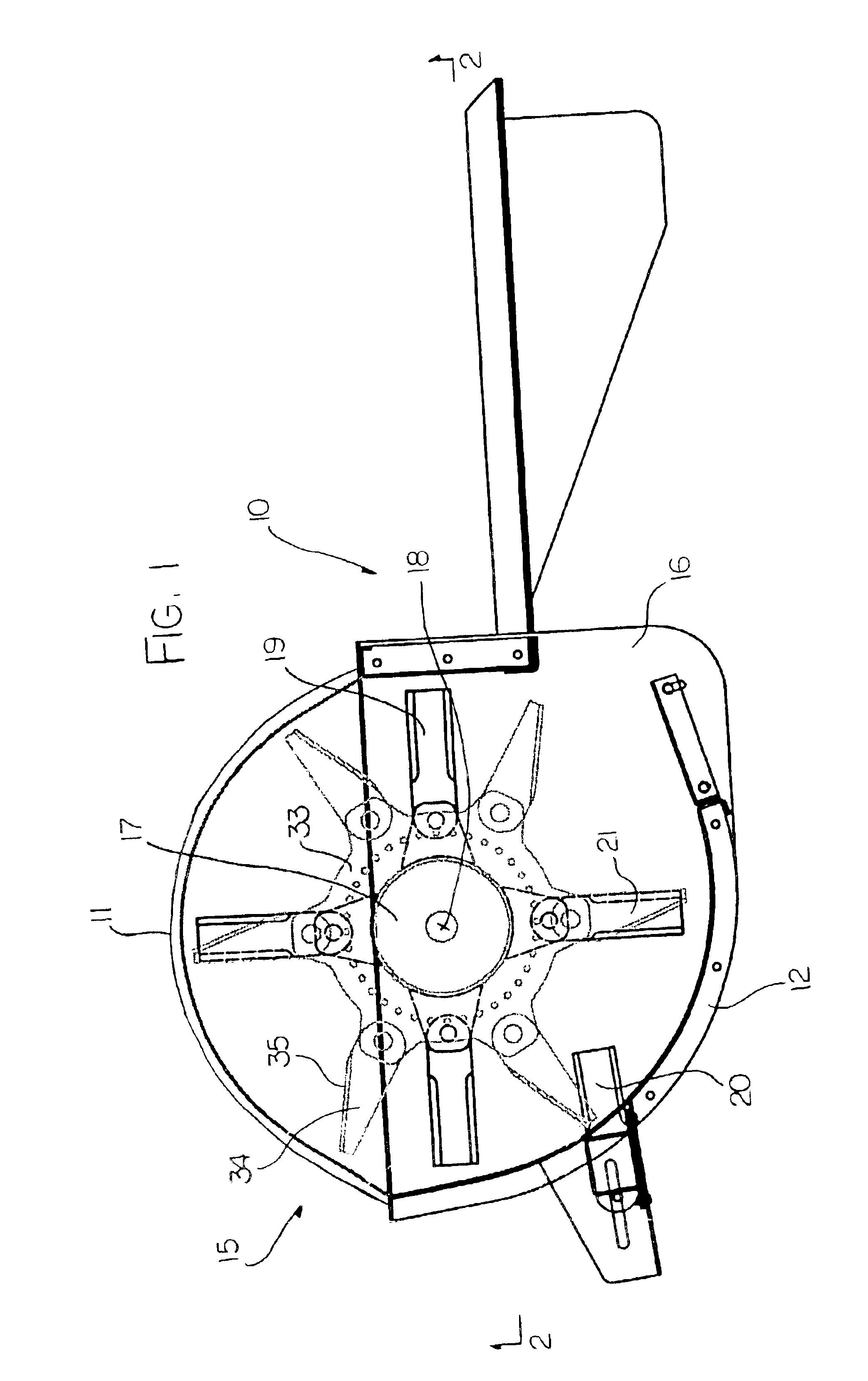
The chopper and discharge arrangement shown in FIG. 1 is very similar to that from the above prior patents of the present inventor which are U.S. Pat. Nos. 5,232,405 and 5,482,508 the disclosures of which is incorporated herein by reference.

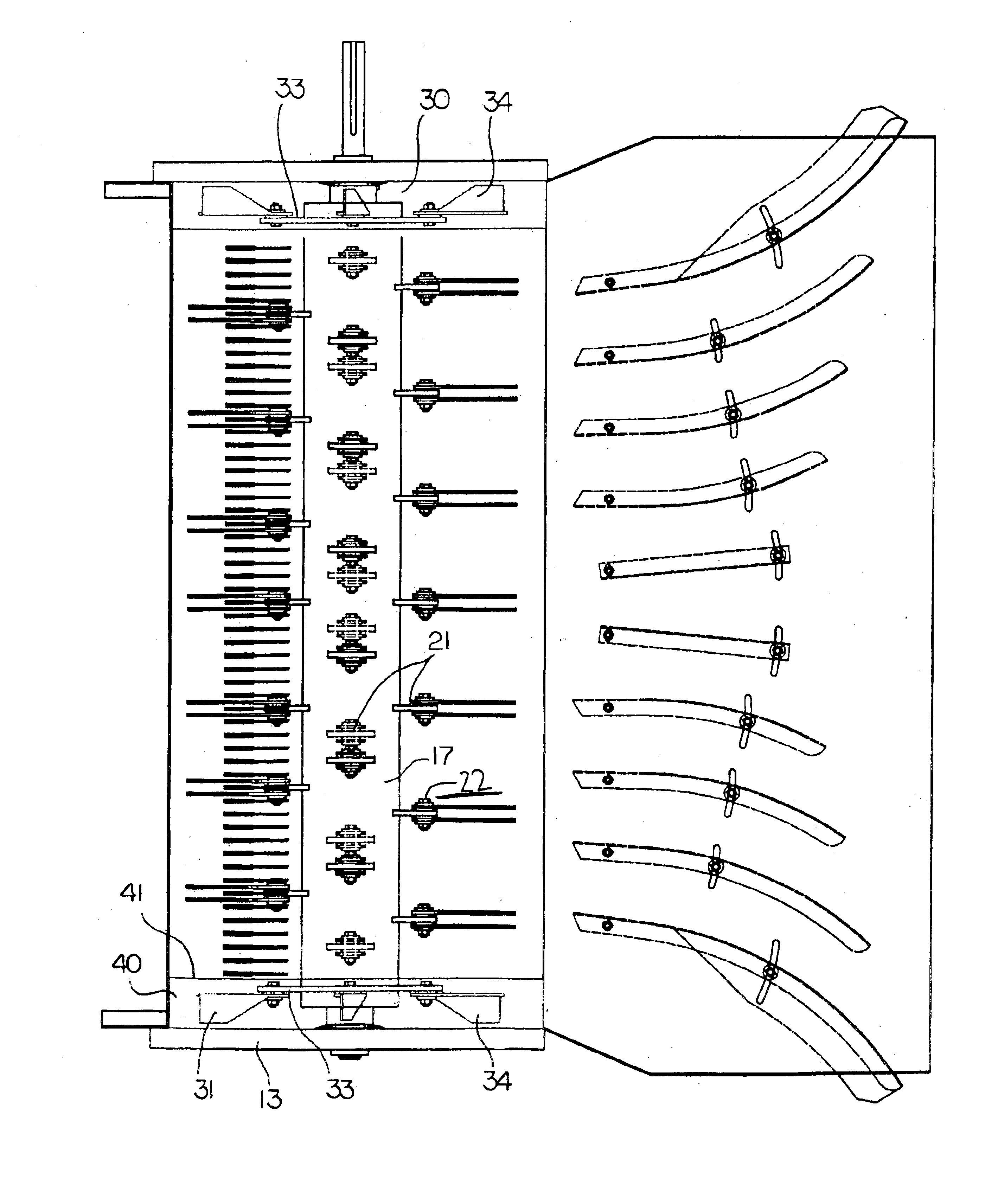
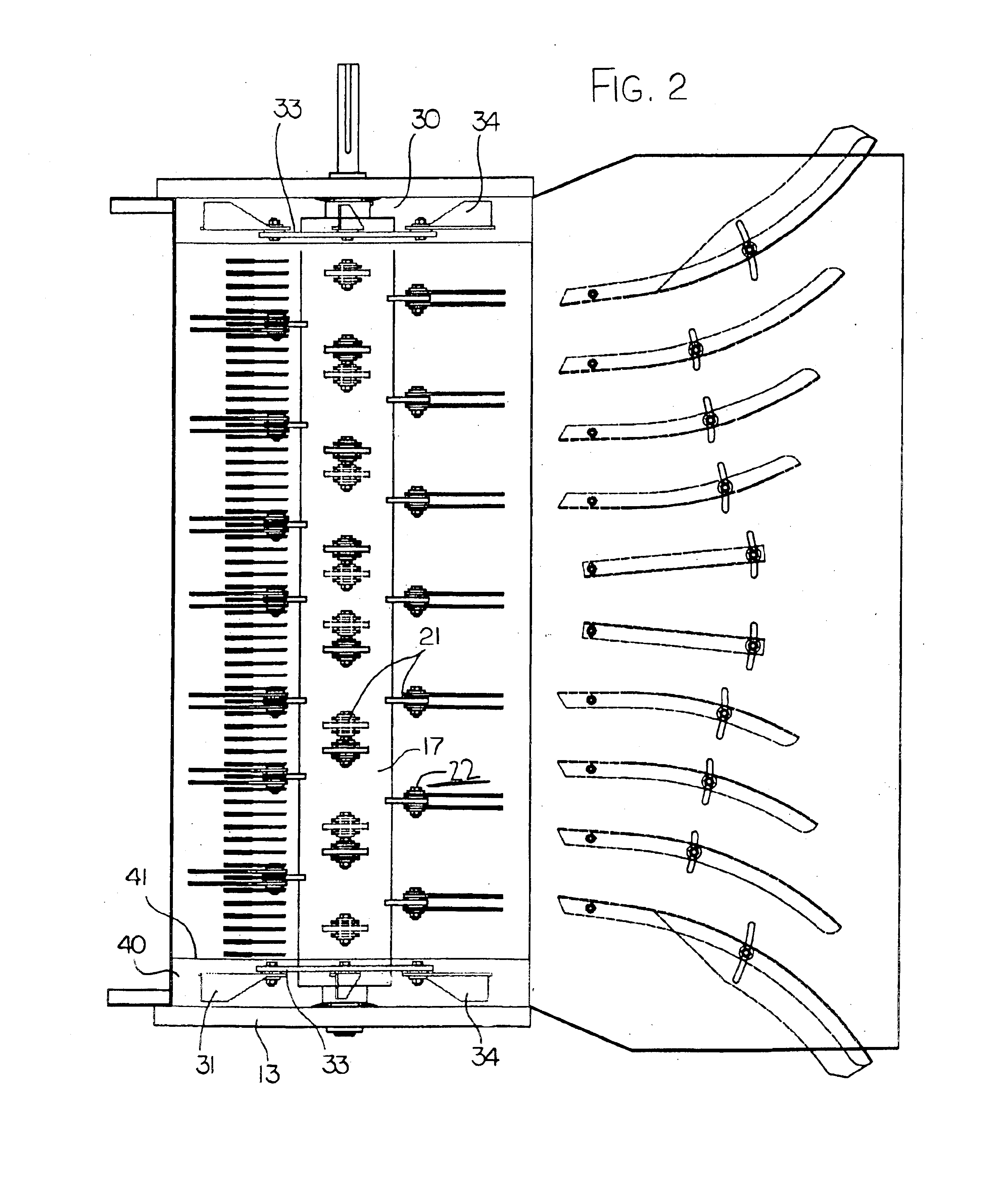
The apparatus therefore comprises a housing 10 defined by a top wall 11, a bottom wall 12 and two end walls 13. The end walls 13 include attachment means schematically for attachment of the housing to the outlet of a combine harvester for discharge of straw and possibly chaff from the combine harvester into an inlet opening 15 of the housing 10. The bottom wall 12 defines a semi-cylindrical portion extending from the inlet 15 to an outlet 16 through which chopped straw and air is discharged at relatively high velocity for spreading across the field or for transportation into a container.

Within the housing is mounted a hub 17 which is carried on suitable bearings (not shown) for rotation about a hub axis 18 at a center of the housing so that blade...


PUM


Abstract

A chopper and discharge apparatus includes a stationary housing for attachment to the rear discharge of a combine harvester so that straw is fed from the combine into an inlet of the housing and is discharged from an outlet of the housing. Within the housing is mounted a hub for rotation about the horizontal axis with the hub carrying a plurality of lugs at angularly and axially spaced positions therearound, each lug carrying a pair of pivotal blade members which are rotated with the hub in the form of flails. Each lug is associated with a stationary blade on the inside of the housing so that the pair of blades carried on each lug sweep past the stationary blade each on a respective side of the stationary blade. The blade members include some flat cutting blades in a center section and only fan blades in end fan sections.

Description

This invention relates to an apparatus for chopping and discharging straw from a combine harvester of the type which includes a plurality of blade members mounted on a hub for rotation about an axis of the hub with the blade members being arranged at spaced positions along the length of the hub substantially in radial planes of the hub so as to pass adjacent a plurality of axially spaced stationary blades again arranged in radial planes of the hub. The straw and other material discharged from the combine is fed into one side of the housing of the apparatus onto the hub and the material is carried around by the hub past the stationary blades in a chopping action. The material is then discharged from a discharge opening in the housing for collection or spreading across the field.BACKGROUND OF THE INVENTIONThe present invention is particularly a modification of or an improvement over the arrangements disclosed in U.S. Pat. No. 5,232,405 issued Aug. 3, 1993 and U.S. Pat. No. 5,482,508 i...

Claims


Application Information

Patent Timeline
Patent Type & Authority Patents(United States)
IPC IPC(8): A01F12/40
CPCA01F12/40
Inventor REDEKOP, LEO
Owner TRITANA HLDG LTD
Why Eureka
Try Eureka