Floating combine sieve assembly

a technology of combine sieve and sieve body, which is applied in the direction of baling, solid separation, agriculture tools and machines, etc., can solve the problems of reducing the effectiveness of the separation between chaff and threshed grain, cumbersome operation, and complicated mechanism and expensive manufacturing. , to achieve the effect of increasing efficiency, preventing chaff from falling, and increasing separation efficiency

Inactive Publication Date: 2005-01-18
SACQUITNE DAVID
View PDF17 Cites 51 Cited by
  • Summary
  • Abstract
  • Description
  • Claims
  • Application Information

AI Technical Summary

Benefits of technology

It is important that as the planks pivot, undesired material such as chaff does not fall between the planks and become mixed with the separated grain below. To prevent this, longitudinal dividers extend the length of the sieve frame between the planks. Elastomeric strips are wrapped over the dividers and connect the adjacent sieve planks. The elastomeric strips allow the planks pivot freely while preventing chaff from falling between the planks.
The leveling mechanism of the present invention prevents grain from being pulled toward the downhill side of the sieve assembly, which in turn increases efficiency by employing the entire surface area of the sieve. Because of the increased separation efficiency, the farmer will not have to slow down when using the combine on a hill.

Problems solved by technology

However, a large percentage of the tillable acreage in the United States has hillside grades and terraces.
This reduces the effectiveness of the separation between the chaff and the threshed grain.
This uneven distribution of the grain on the sieves forces farmers to slow down so that the grain does not build up on the downhill side of the combine to the point where grain is lost from the combine.
However, this mechanism is complicated and expensive to manufacture as well and cumbersome in operation.
The problem with the device described in this patent is that the electronic sensing means and the electric motors that pivot the sieve sections are expensive to install and to operate.
This lag time can lead to inefficient separating of grain.
Although this device may direct falling grain to the uphill side of the sieves, the device is inefficient because once the grain falls onto the sieves, gravity will pull it to the downhill side of the combine, resulting in grain buildup on the downhill side.
The problem with these devices is that the collected grain is directed toward the center of the sieve rather than toward the high edge of the sieve, and therefore these devices only take advantage of half of the sieve's surface area.

Method used


Image

  • Floating combine sieve assembly
  • Floating combine sieve assembly
  • Floating combine sieve assembly

Examples


Embodiment Construction

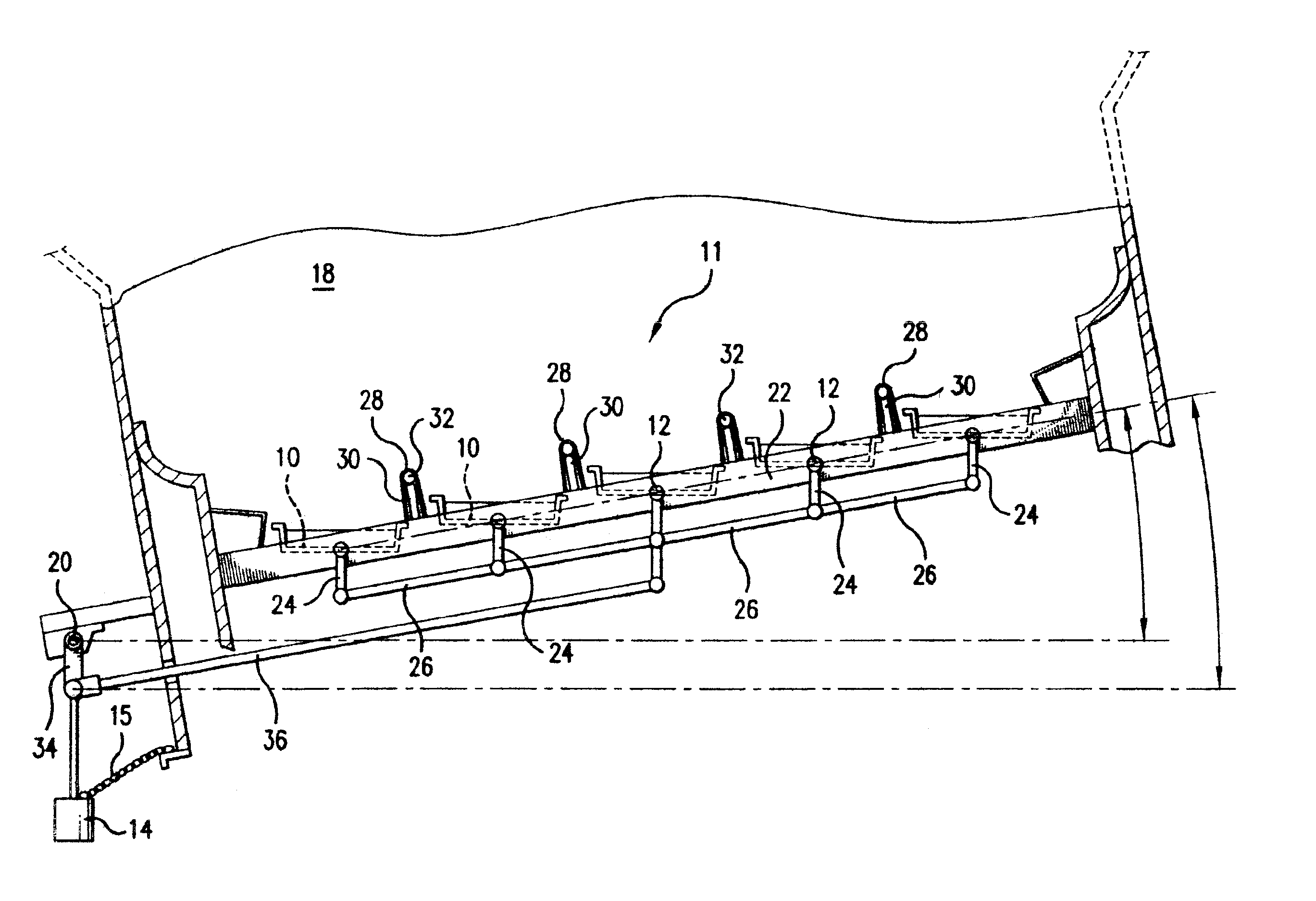
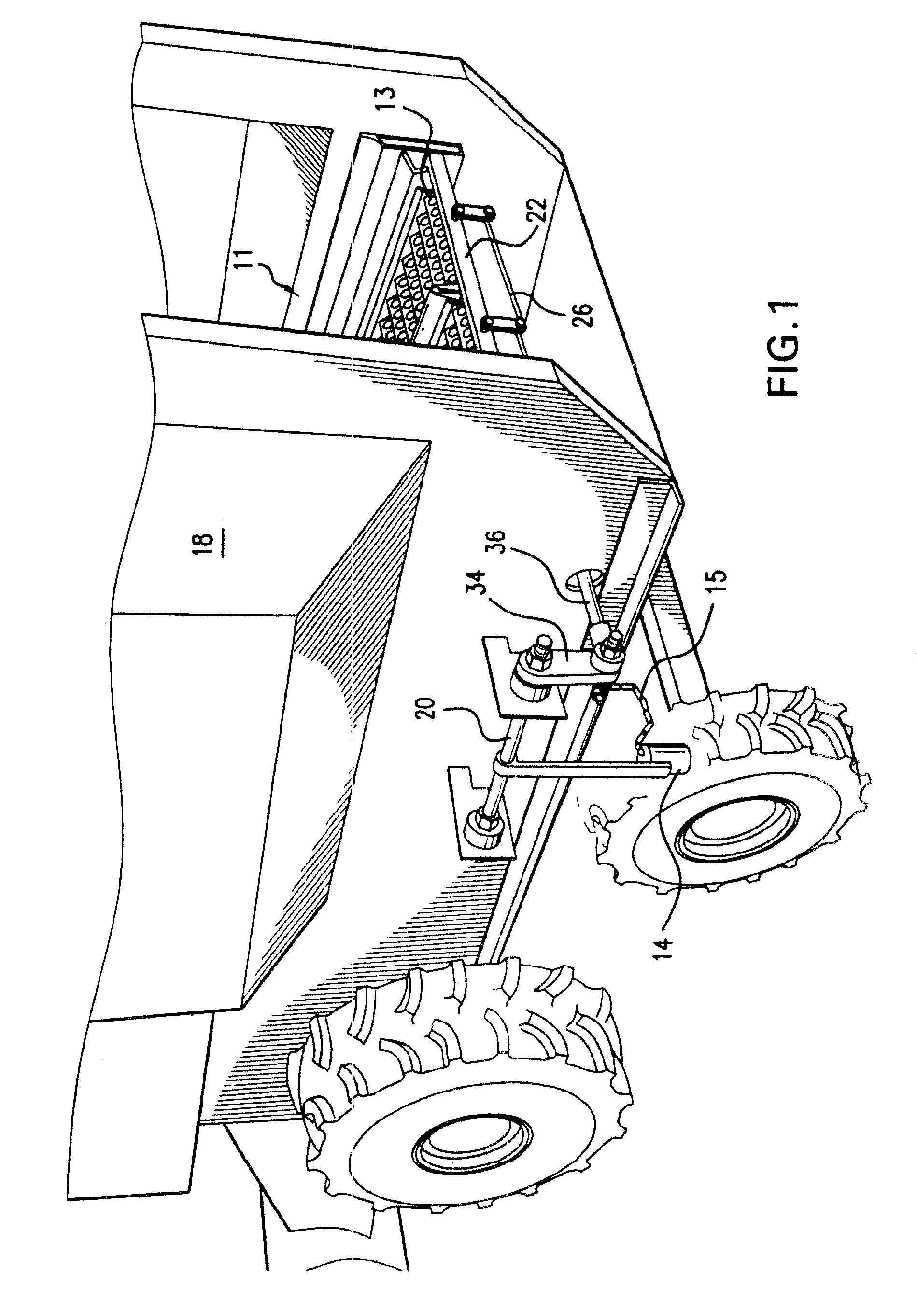
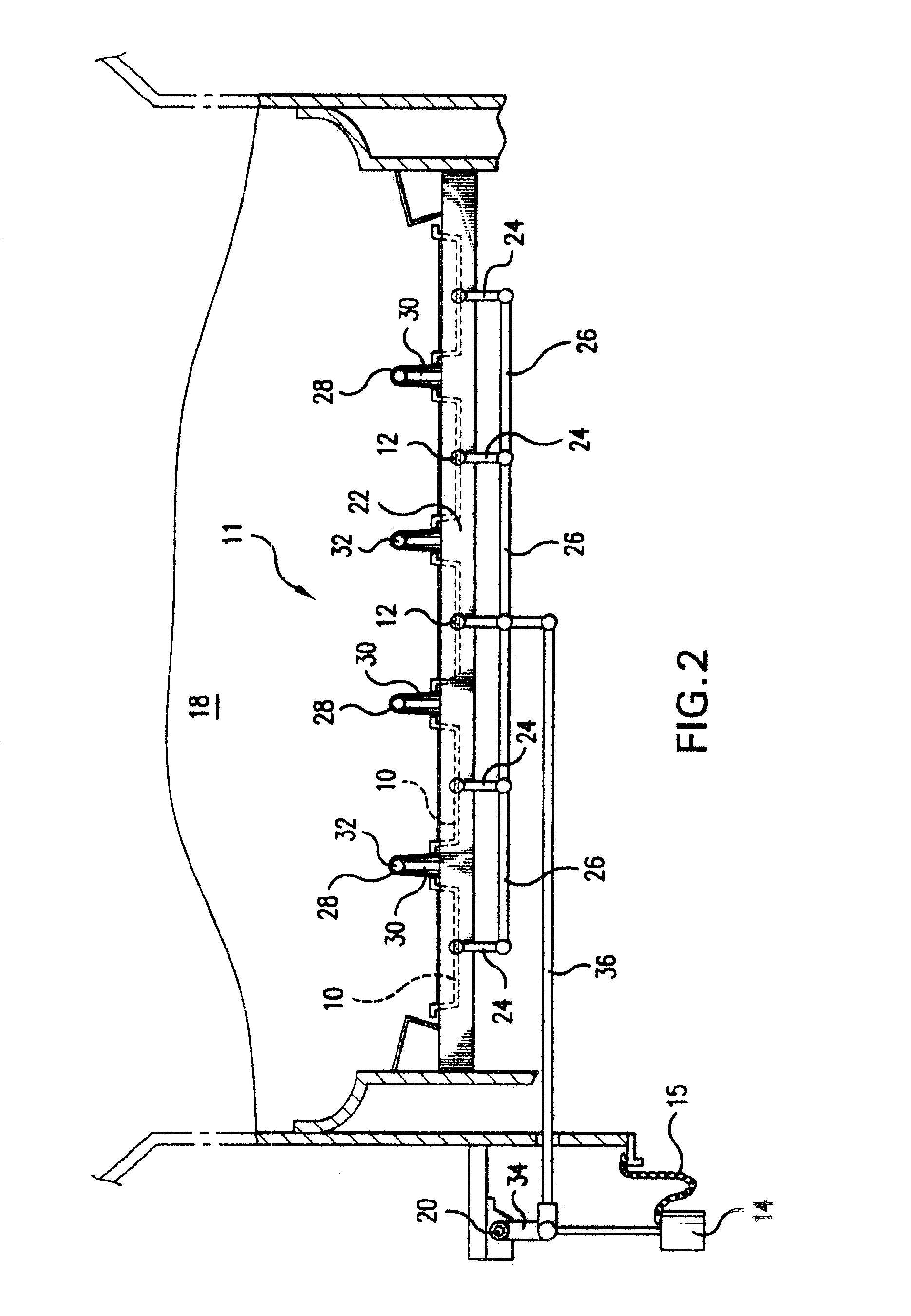
FIG. 1 shows a combine 18 having a leveling mechanism for a sieve assembly 11 as herein described. In a combine's basic operation, the combine 18 cuts the crop, threshes the crop, and then delivers the threshed crop onto a sieve 11 for separating the grain from the chaff. This sieve 11 separation is a gravity separation in which the desired grain particles are smaller than the chaff. The sieve 11 has a top surface with a plurality of oblong holes 13 which are large enough to allow threshed grain to fall through, yet not large enough to allow chaff to fall through. The oblong shape of the holes 13 allows the grain to efficiently fall through the sieve 11 by preventing the grain from gathering on top of the sieve 11. The oblong holes 13 are angled toward the back of the combine so that as air is blown upward through the holes 13, the chaff is directed to the back and eventually out of the combine 18. These angled holes 13 allow for efficient cleaning of the grain because the chaff is ...


PUM


Abstract

A sieve assembly for separating grain from chaff inside of a combine. The sieve assembly comprises a plurality of longitudinal sieve planks that pivot on their longitudinal axis. A hanging weighted member combined with the sieve planks regulates the angle of the sieve planks relative to the combine. As the combine becomes laterally inclined on a hillside, the weighted member changes its angular position relative to the combine. In doing so, the weighted member causes the sieve planks to pivot on their longitudinal axis so that the sieve planks remain level relative to the horizon. Dividers extend between each sieve plank.

Description

BACKGROUND OF INVENTIONThe present invention relates generally to combine harvesters and, more particularly, to improvements in their cleaning apparatus to permit a leveling thereof under side hill conditions.Combines of the type concerned herein are large, self-propelled vehicles for cutting and threshing grain. A combine has a header which has a blade that will cut the crop. An auger mounted to the header delivers the crop up into a threshing chamber. The threshed grain falls onto a set of upper and lower sieves. The sieves separate the grain from the chaff, with the grain falling through the holes in the sieve into a collection area. Air is blown upward through the sieve holes so that the chaff is blown from the combine.A combine works best while it is level. The grain is evenly distributed across the sieves while the sieves are level. However, a large percentage of the tillable acreage in the United States has hillside grades and terraces. Often it is necessary to cut the hillsi...

Claims


Application Information

Patent Timeline
Patent Type & Authority Patents(United States)
IPC IPC(8): A01D75/00A01D75/28
CPCA01D75/282
Inventor SACQUITNE, DAVID
Owner SACQUITNE DAVID
Why Eureka
Try Eureka