Fluid-dynamic renewable energy harvesting system

Active Publication Date: 2009-05-21
RIC ENTERPRISES
View PDF34 Cites 56 Cited by
  • Summary
  • Abstract
  • Description
  • Claims
  • Application Information

AI Technical Summary

Benefits of technology

[0005]The invention provides a fluid-dynamic renewable energy harvesting system which includes fluid-foil means for interfacing with a fluid current such as a water current or wind or both, and which includes energy harvesting means utilizing fluid current driven periodic motion of the fluid-foil means, for capturing fluid-dynamic renewable energy and converting it into usable energy in a desired form such as electricity. The invention provides devices, methods and systems for h

Problems solved by technology

The continued use of fossil fuels to meet current and emerging energy needs also has very negative environmental consequences, inclu

Method used


Image

  • Fluid-dynamic renewable energy harvesting system
  • Fluid-dynamic renewable energy harvesting system
  • Fluid-dynamic renewable energy harvesting system

Examples


Embodiment Construction

[0046]The following section of the specification presents a detailed description of the invention and its various preferred embodiments, with reference to the attached Figures illustrating the invention.

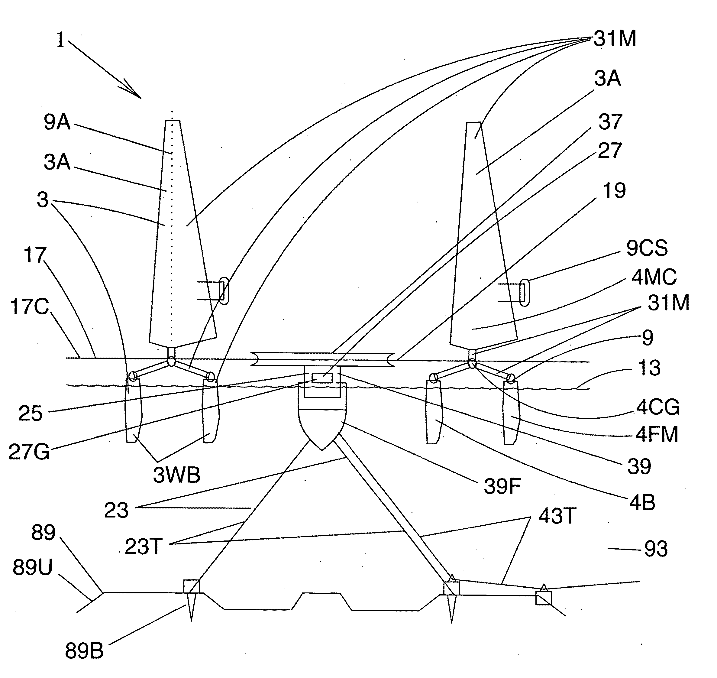
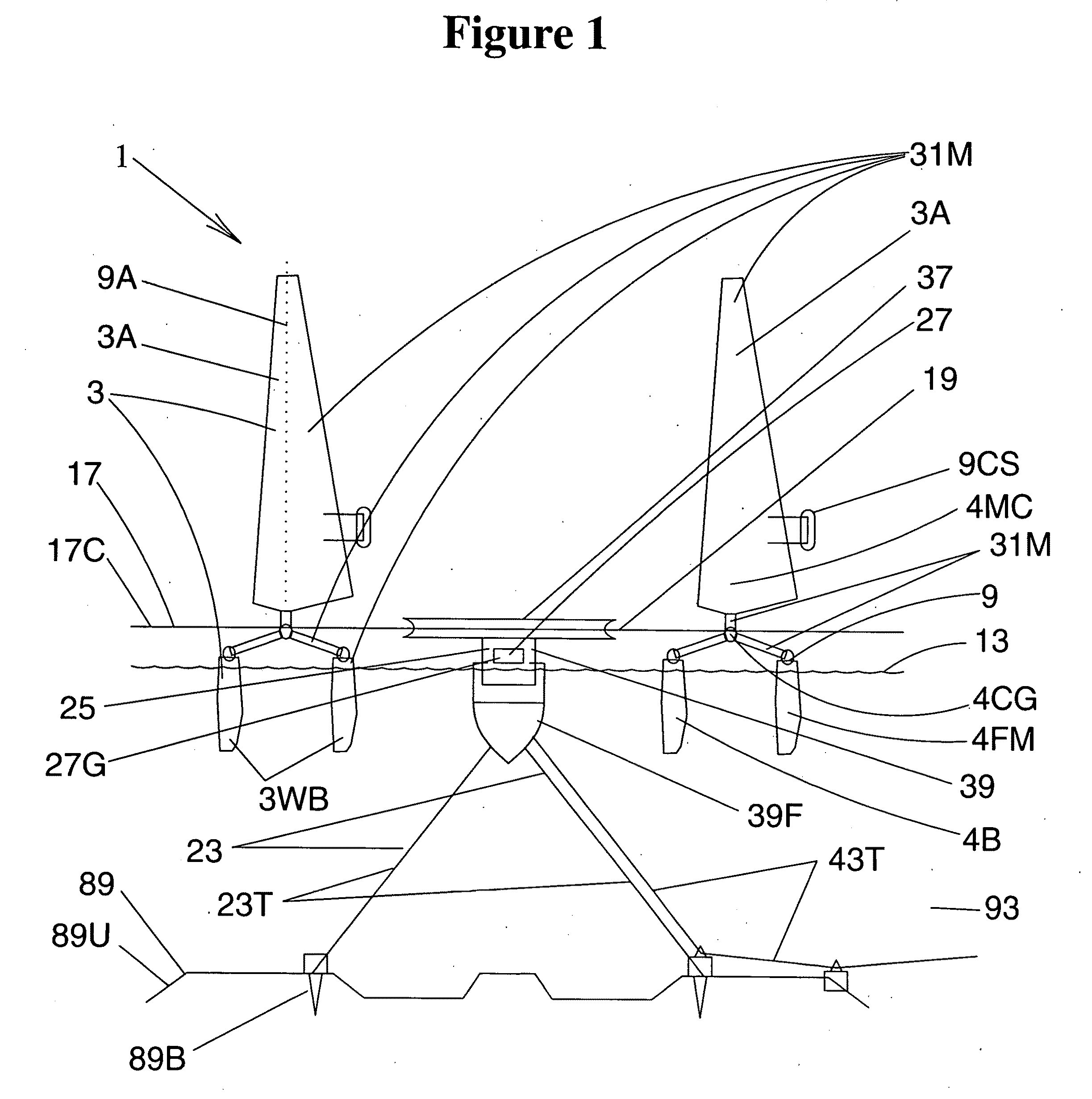
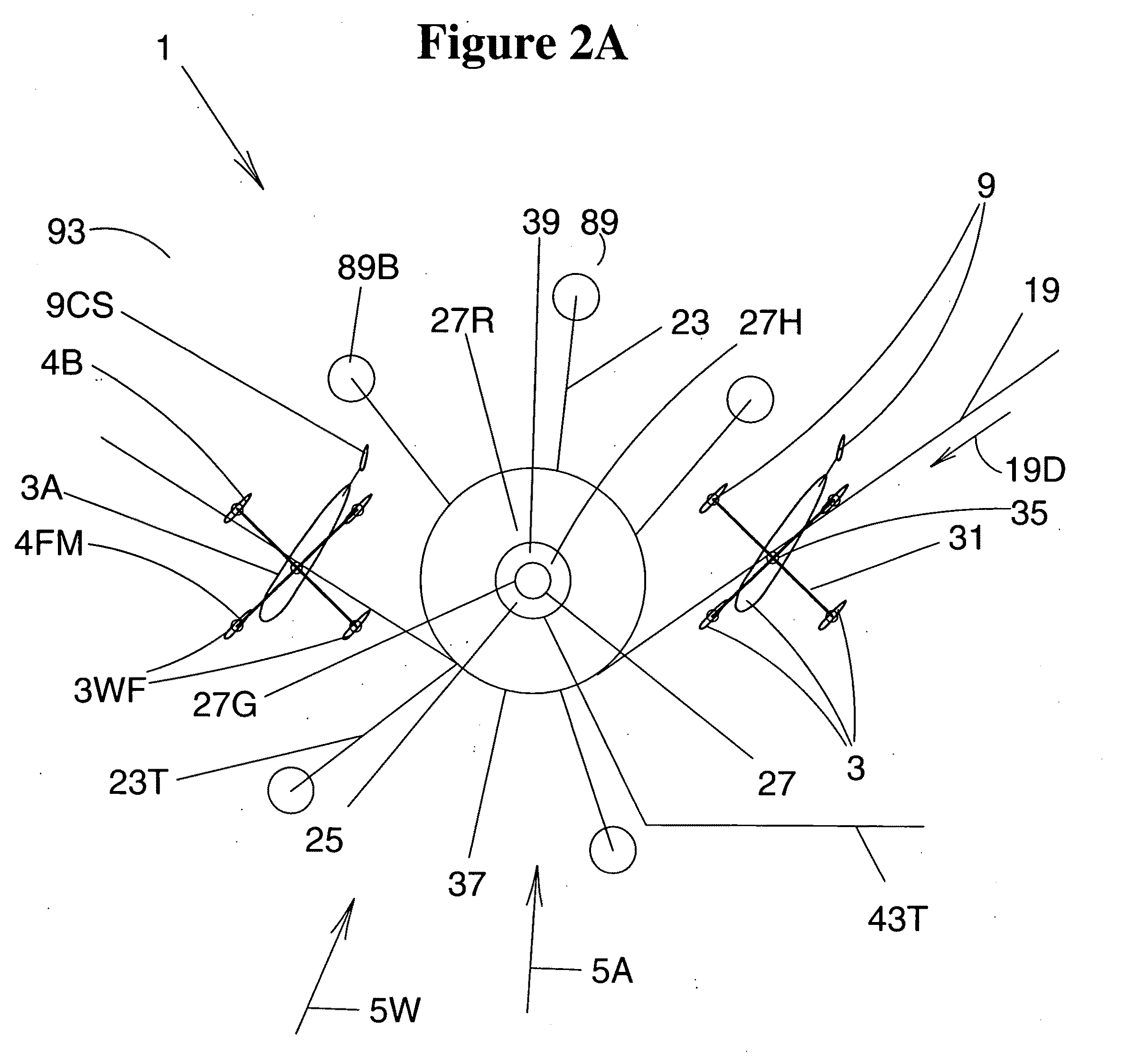
[0047]FIG. 1 shows a side view of a portion of one preferred embodiment of a fluid-dynamic renewable energy harvesting system.

[0048]FIG. 1 illustrates two of a plurality of movable members 31M for a fluid-dynamic renewable energy harvesting system 1. The movable member 31M include fluid-foil means 3 for interfacing with a fluid current, wherein the illustrated fluid-foil means for interfacing with a fluid current include buoyant hydrofoils 3WB for interfacing with a water current in a body of water below a water surface 13. In the illustrated embodiment four approximately vertically oriented buoyant hydrofoils 3WB are used to contribute to buoyancy, which buoyancy provides support forces acting towards supporting the movable members 31M. For each movable member 31M, two of four buoya...


PUM


Abstract

The invention provides a fluid-dynamic renewable energy harvesting system which includes fluid-foil means for interfacing with a fluid current such as a water current or wind or both, and which includes energy harvesting means utilizing fluid current driven periodic motion of the fluid-foil means for capturing fluid-dynamic renewable energy and converting it into usable energy in a desired form such as electricity. The invention provides devices, methods and systems for harvesting renewable energy for small-scale, medium-scale and large-scale applications, to provide real and substantial benefits towards efficiently fulfilling energy needs while also more broadly serving humanity and our global environment. The various embodiments of the invention provide energy with zero consumption of fossil fuels and zero emissions of greenhouse gases, and some selectively sited embodiments can beneficially counter global warming induced ice melting.

Description

CROSS-REFERENCE TO RELATED PATENT APPLICATIONS[0001]This patent application entitled “FLUID-DYNAMIC RENEWABLE ENERGY HARVESTING SYSTEM” is being filed simultaneously with the related patent application entitled “WIND ENERGY HARVESTING SYSTEM ON A FROZEN SURFACE” also invented by Mithra M. K. V. Sankrithi and hereby incorporated herein by reference.BACKGROUND OF THE INVENTION[0002]As the World's human population grows and as the economic prosperity of our global population grows, the energy demand of our global population also grows. With limited availability of oil reserves, there is a growing need for the conception, development and deployment of cost-effective and large-scale renewable energy alternatives. The continued use of fossil fuels to meet current and emerging energy needs also has very negative environmental consequences, including massive emissions of carbon dioxide and other pollutants, along with exacerbation of global warming and climate change effects. These factors ...

Claims


Application Information

Patent Timeline
IPC IPC(8): F03B13/10F03D9/00
CPCE02B2017/0091F03B13/264F03D5/02F05B2240/311F05B2240/40Y02E10/28F05B2240/932F05B2240/95Y02E10/70Y02E10/721F05B2240/93Y02E10/30Y02E10/727Y02E10/20Y02E10/72
Inventor SANKRITHI, MITHRA M.K.V.
Owner RIC ENTERPRISES
Why Eureka
Try Eureka