Ir reflecting grating for halogen lamps

a technology of halogen lamps and gratings, which is applied in the field of illumination arts, can solve the problems of time-consuming and labor-intensive process of forming multi-layer coatings and add significant costs to lamps

Inactive Publication Date: 2009-05-28
GENERAL ELECTRIC CO
View PDF10 Cites 9 Cited by
  • Summary
  • Abstract
  • Description
  • Claims
  • Application Information

AI Technical Summary

Problems solved by technology

The process of forming the multi-layer coating is time intensive and generally requires high vacuum techniques, adding a significant cost to the lamp.

Method used


Image

  • Ir reflecting grating for halogen lamps
  • Ir reflecting grating for halogen lamps
  • Ir reflecting grating for halogen lamps

Examples


example

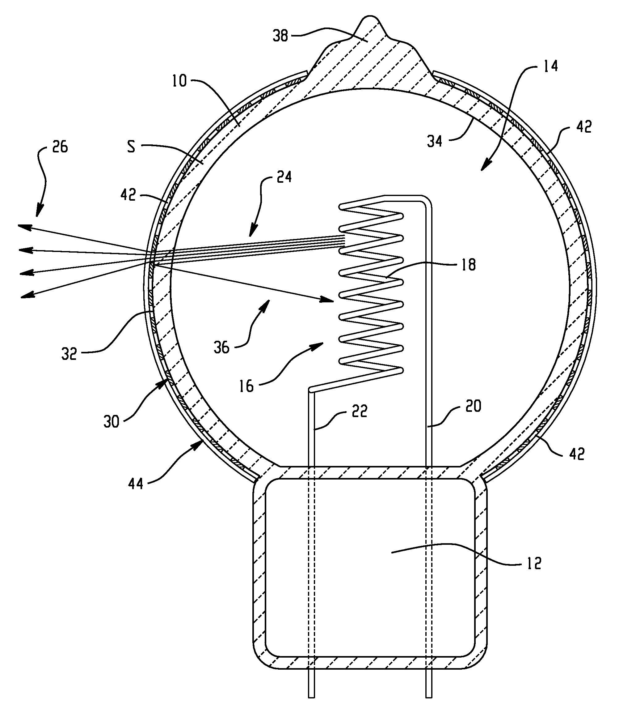
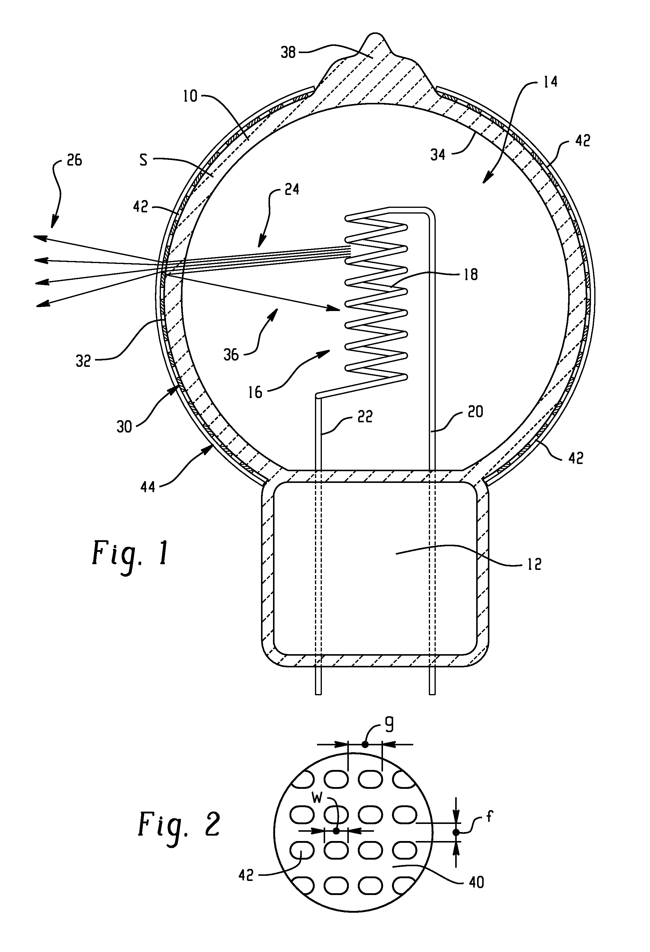
[0055]To model the exemplary lamp of FIG. 1, a bulb of a conventional halogen lamp (G4 single ended quartz (SEQ) lamp) was covered with an optical grating by applying a thin pre-patterned film to the lamp bulb exterior surface. The film was formed of a thin metallic layer with holes burned therein on a polymeric substrate. For experimental purposes, the patterned film was simply loosely wrapped around the lamp bulb and the protective coating was not specifically formulated for withstanding high lamp operating temperatures. Prior to applying the film, measurements of the coil temperature using wavelength measurements at 1100 and 1500 nm in both transmitted and reflected light from the film were made. From these measurements, it was determined that the pre-patterned film exhibited good reflectance and poor transmittance in this wavelength range.

[0056]The coated lamp (lamp A) formed in this manner was connected with a DC power source and currents measured at various lamp voltages. Comp...


PUM


Abstract

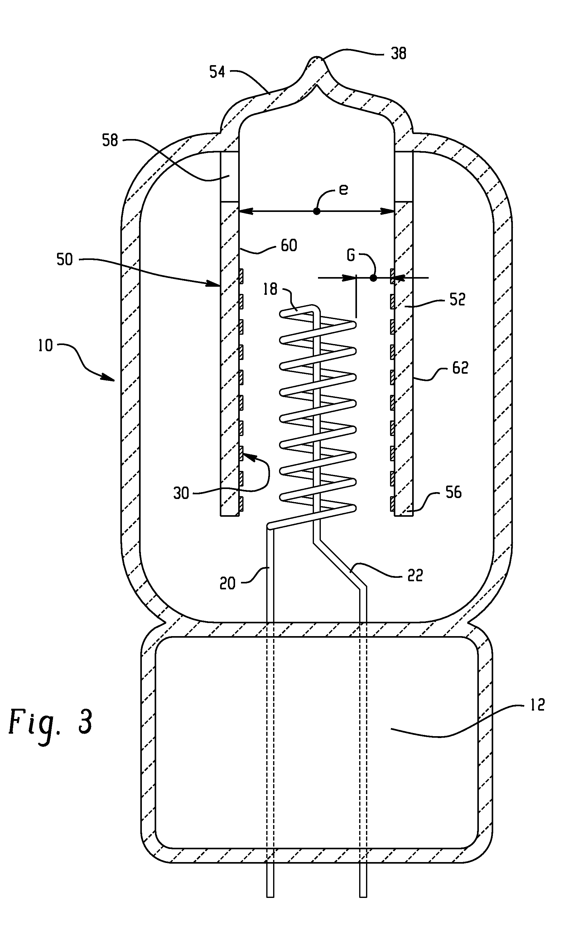
A lamp, such as a halogen lamp, includes a bulb which is sealed to define an interior chamber. An emitter, such as a filament, is disposed within the interior chamber which, during operation of the lamp, emits radiation in the visible and infrared regions of the spectrum. An optical grating, generally spaced from the emitter, is positioned to intercept radiation from the emitter. The optical grating reflects infrared radiation and transmits visible radiation therethrough. In this way, the output of the lamp in the visible range can be increased as compared with an otherwise identical lamp formed without the grating.

Description

BACKGROUND OF THE INVENTION[0001]The exemplary embodiment relates to the illumination arts. It finds particular application in connection with a lamp with an optical grating for increasing efficiency and reducing the emission of infrared radiation from the lamp.[0002]Incandescent halogen lamps radiate a large proportion of their energy as heat, in the infrared (IR) range of the electromagnetic spectrum in accordance with Plank's law. In particular, as the operating temperature the filament increases, the spectral radiance distribution shifts and the peak moves towards shorter wavelengths (in accordance with Wien's law). Even at relatively high operating temperatures of 2,000K-4000K, more of the radiation is emitted in the infrared range than in the visible range.[0003]To reduce the IR emissions and increase the efficiency of the lamp, it is common to provide an IR-reflective coating on the lamp. The coating is formed of multiple alternating layers of materials of high and low refrac...

Claims


Application Information

Patent Timeline
Patent Type & Authority Applications(United States)
IPC IPC(8): H01K1/26H01J9/00
CPCH01J61/025H01J65/00H01J61/35H01J61/34
Inventor CSEH, GEZA Z.NAGY, PETER L.FAZEKAS, FERENC
Owner GENERAL ELECTRIC CO
Why Eureka
Try Eureka