Latch position indicator system and method

a position indicator and position indicator technology, applied in the direction of survey, sealing/packing, borehole/well accessories, etc., can solve the problems of increasing drilling costs, excluding gas hydrates, and a large amount of known resources considered economically undrillable, and increasing the amount of known resources

a position indicator and position indicator technology, applied in the direction of survey, sealing/packing, borehole/well accessories, etc., can solve the problems of increasing drilling costs, excluding gas hydrates, and a large amount of known resources considered economically undrillable, and increasing the amount of known resources

US20090139724A1Active Publication Date: 2009-06-04WEATHERFORD TECH HLDG LLC

Image

  • Latch position indicator system and method
  • Latch position indicator system and method
  • Latch position indicator system and method

Examples


Embodiment Construction

[0076]Although the following is sometimes described in terms of an offshore platform environment, all offshore and onshore embodiments are contemplated. Additionally, although the following is described in terms of oilfield drilling, the disclosed embodiments can be used in other operating environments and for drilling for non-petroleum fluids.

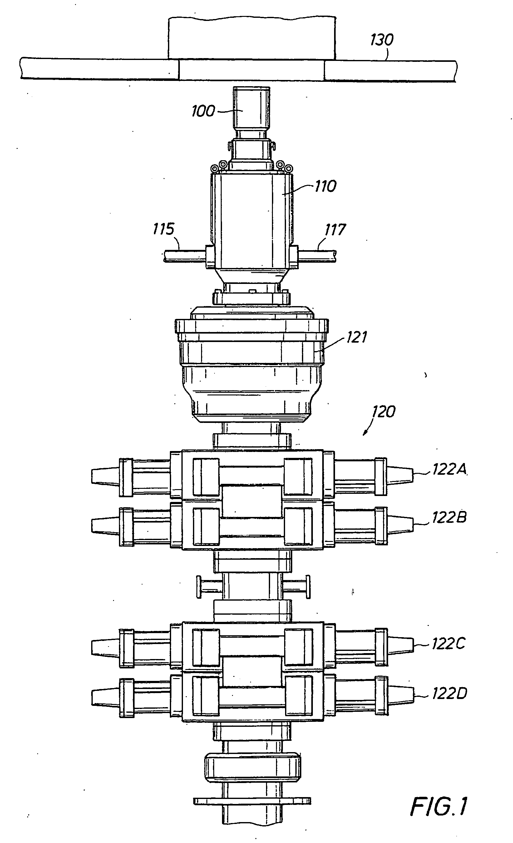
[0077]Turning to FIG. 1, a rotating control device 100 is shown latched into a riser or bell nipple 110 above a typical blowout preventer (BOP) stack, generally indicated at 120. As illustrated in FIG. 1, the exemplary BOP stack 120 contains an annular BOP 121 and four ram-type BOPs 122A-122D. Other BOP stack 120 configurations are contemplated and the configuration of these BOP stacks is determined by the work being performed. The rotating control device 100 is shown below the rotary table 130 in a moon pool of a fixed offshore drilling rig, such as a jackup or platform rig. The remainder of the drilling rig is not shown for clarity of the fi...


PUM


Abstract

Latch position indicator systems remotely determine whether a latch assembly is latched or unlatched. The latch assembly may be a single latch assembly or a dual latch assembly. An oilfield device may be positioned with the latch assembly. Non-contact (position), contact (on / off and / or position) and hydraulic (flowmeter), both direct and indirect, embodiments include fluid measurement systems, an electrical switch system, a mechanical valve system, and proximity sensor systems.

Description

CROSS-REFERENCE TO RELATED APPLICATIONS[0001]This application is: (1) a continuation-in-part of U.S. application Ser. No. 10 / 995,980 filed on Nov. 23, 2004, now U.S. Pat. No. 7,487,837; and this application is (2) a continuation-in-part of co-pending U.S. application Ser. No. 11 / 366,078 filed on Mar. 2, 2006, which is a continuation-in-part of U.S. application Ser. No. 10 / 995,980 filed on Nov. 23, 2004, now U.S. Pat. No. 7,487,837, all of which applications are hereby incorporated by reference for all purposes in their entirety and are assigned to the assignee of the present invention.STATEMENT REGARDING FEDERALLY SPONSORED RESEARCH OR DEVELOPMENT[0002]N / AREFERENCE TO MICROFICHE APPENDIX[0003]N / ABACKGROUND OF THE INVENTION[0004]1. Field of the Invention[0005]The present invention relates to the field of oilfield drilling equipment, and in particular to rotating control devices.[0006]2. Description of the Related Art[0007]Conventional offshore drilling techniques involve using hydrau...

Claims


Application Information

Patent Timeline
04 Jun 2009
Publication
US20090139724A1
IPC
E21B29/12; E21B43/01; E21B47/09
CPC
E21B23/04; E21B33/085; E21B47/0001; E21B47/09; E21B43/013; E21B34/045; E21B47/001
Inventors
GRAY, KEVIN L.; BAILEY, THOMAS F.