Pressure sensor

a technology of pressure sensor and pressure sensor, which is applied in the direction of fluid pressure measurement, instruments, braking systems, etc., can solve the problems of signal transmission or electrical connection instability, easy generation of contact errors, and inability of the driver to steer the vehicle in the desired direction, etc., and achieve the effect of convenient insertion

Inactive Publication Date: 2009-06-04
HL MANDO CORP
View PDF17 Cites 13 Cited by
  • Summary
  • Abstract
  • Description
  • Claims
  • Application Information

AI Technical Summary

Benefits of technology

[0017]The present invention is conceived to solve the aforementioned problems in the prior art. According to one embodiment, a pressure sensor is provided, which can be in stable connect with a circuit board of an electronic control unit, has a simple coupling structure without soldering, and can be securely mounted to prevent signal transmission or electrical connection caused by vibration and the like from being interrupted.
[0018]According to one embodiment, a pressure sensor has an improved inner structure to allow the pressure sensor to be stably connected to a circuit board, can prevent a coupling error from occurring to easily perform an assembling process, and can absorb lateral vibration.
[0020]Further, the press-fit terminal preferably comprises a central portion having a lower end coupled to the connecting terminal of the circuit board and electrically connected thereto, and a pair of extension portions extending upward from both sides of the central portion, the press-fit terminal having elasticity for allowing the ends of the extension portions to be in elastic contact with the press-fit. Furthermore, the press-fit terminal may comprise a guide portion formed on the end of the extension portion to be inclined outwardly for allowing the press-fit to be easily inserted thereinto.

Problems solved by technology

In the meantime, in a state where the brake operates as described above, a steering system becomes locked, and thus, the driver cannot steer the vehicle in his or her desired direction.
However, the pressure sensor 10 according to the prior art has a problem in that if large vibration is generated, the springs 20 and 24 may be compressed and thus the pin member 24 may be separated from the circuit board of the electronic control unit.
Also, in the conventional pressure sensor 10, the pin members 24 are not accurately connected to terminals of the circuit board, whereby signal transmission or electrical connection becomes unstable due to a contact error caused by the inaccurate connection.
Furthermore, in the conventional pressure sensor 10, since the pin members 24, which are in contact with the circuit board, are made of a rigid material, when shock is applied, the pin members 24 are inertially moved by vibration and the like, so that a contact error can be easily generated.
There is a problem in that a connecting terminal of the circuit board is damaged by shock or friction generated between the pin members 24 and the circuit board.
Also, there is a problem in that when lateral vibration is generated, the conventional pressure sensor 10 cannot absorb this lateral vibration appropriately.
As described above, if the contact error between the conventional pressure sensor 10 and the electronic control unit is generated, this contact error acts as the factor affecting the steering and braking performances of a vehicle.

Method used


Image

  • Pressure sensor
  • Pressure sensor
  • Pressure sensor

Examples


first embodiment

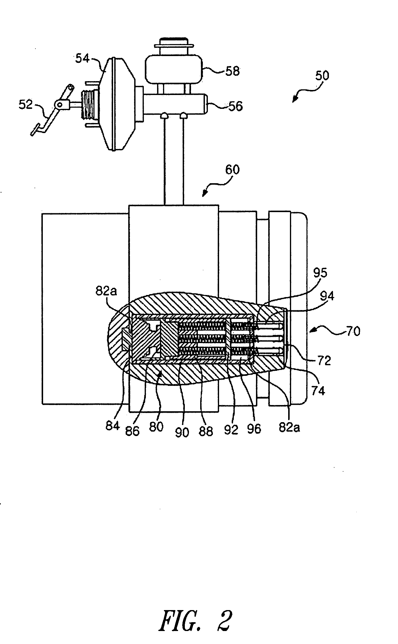
[0031]FIG. 2 is a view of the configuration of an anti-lock brake system, showing a pressure sensor according to the present invention.

[0032]As shown in FIG. 2, a pressure sensor 80 according to one embodiment is mounted to a hydraulic unit 60 of an anti-lock brake system 50. The anti-lock brake system 50 comprises the hydraulic unit 60 to which a plurality of solenoid valves, low-pressure accumulators and high-pressure accumulators for adjusting brake oil pressure to be transmitted to the wheel brake, and an electronic control unit (ECU) 70 for controlling components that electronically operate.

[0033]The solenoid valve of the hydraulic unit 60 can adjust brake oil pressure of a wheel brake installed on a wheel. The wheel brake is rubbed with a wheel by the oil pressure of the solenoid valve to directly generate braking force. To this end, a pump for pumping brake oil is connected to the solenoid valve. The operation of the solenoid valve or the pump is electrically controlled by th...

second embodiment

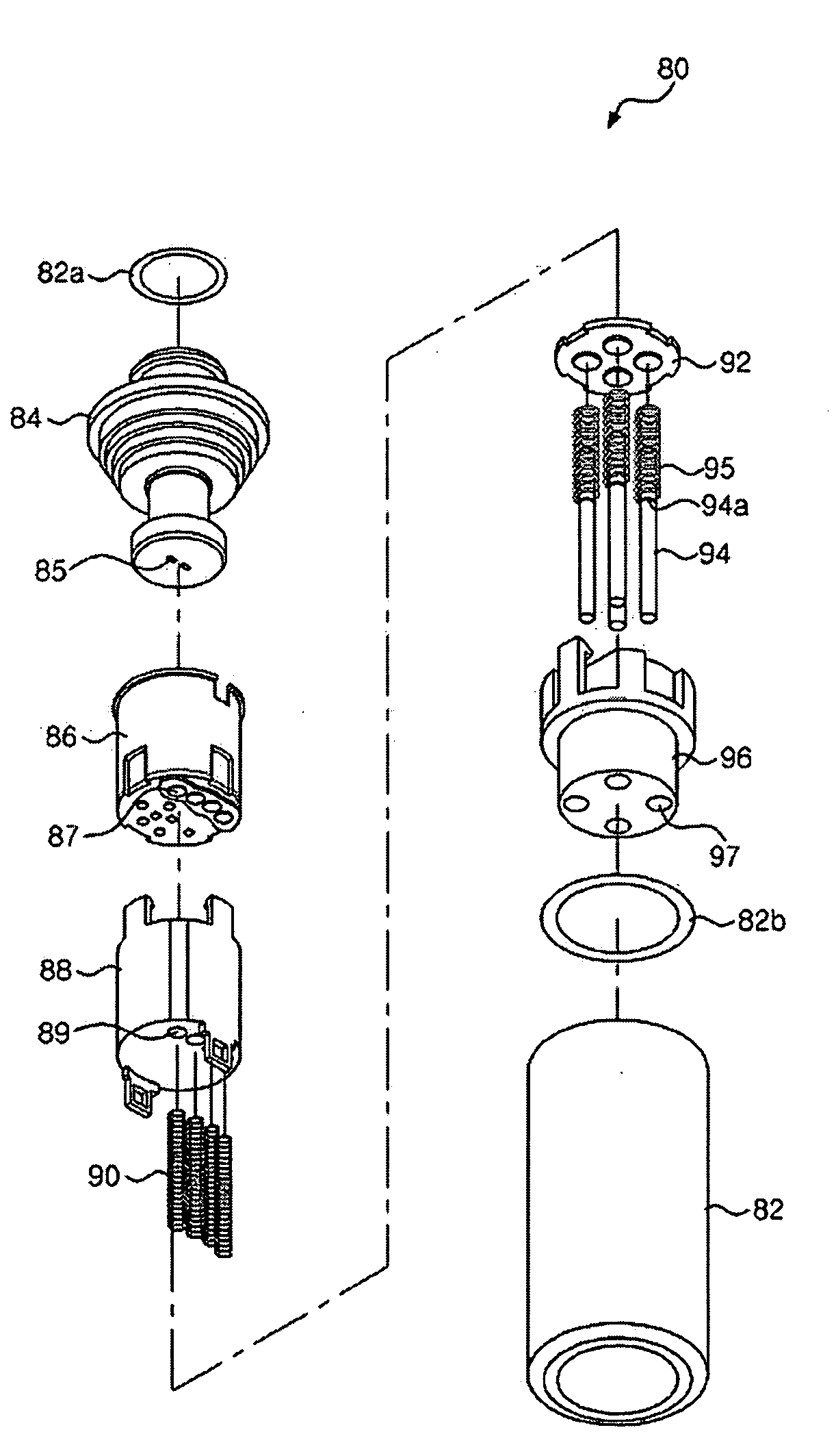
[0058]The pressure sensor 50 of this embodiment differs from and the pressure sensor according to the aforementioned embodiment in the connecting member connected to the circuit board of the electronic control unit. In other words, there is a difference in that the second embodiment has no press-fit employed therein and no press-fit terminal provided on the circuit board of the electronic control unit.

[0059]The connecting member is provided with the upper guide 88 coupled to the lower portion of the electric component module 86 and the contact board 92 at the lower portion of the upper guide 88. The upper guide 88 is provided with the connecting members 90 for connecting the contact board 92 and the connecting terminals 87 provided at the lower portion of the electric component module 86. In order to stably transmit the signal when the contact board 92 is vibrated, springs 90 may be employed as the connecting members 90. Furthermore, the upper guide 88 is formed with a plurality of ...


PUM

PropertyMeasurementUnit
pressureaaaaaaaaaa
elasticityaaaaaaaaaa
winding densityaaaaaaaaaa

Abstract

The present invention relates to a pressure sensor employed in a stability control apparatus for a vehicle. According to an aspect, there is provided a pressure sensor installed to a hydraulic unit and being in contact with a circuit board of an electronic control unit to sense brake oil pressure. The pressure sensor comprises a connecting terminal formed on the circuit board of the electronic control board and comprising a press-fit terminal; a press-fit being in slidable and movable contact with the press-fit terminal; and a spring connecting the press-fit and the press-fit terminal.

Description

BACKGROUND OF THE INVENTION[0001]1. Technical Field[0002]The present invention relates to a pressure sensor employed in a stability control apparatus for a vehicle, and more particularly, to a pressure sensor, which makes it possible to be in stable contact with an electronic control unit under a condition where an excessive vibration is generated.[0003]2. Description of the Related Art[0004]In general, a vehicle is provided with a brake system for reducing speed or braking. The brake system comprises a pedal for transmitting driver's operating force, a booster and a master cylinder connected to the pedal to generate brake oil pressure, and a wheel brakes for braking wheels of the vehicle according to the brake oil pressure inputted from the booster and the master cylinder.[0005]In the brake system, when the driver steps on the brake pedal to generate the braking force, if the braking force is larger than a road friction force or the friction force generated on the wheel brake by th...

Claims


Application Information

Patent Timeline
Patent Type & Authority Applications(United States)
IPC IPC(8): B60T13/68G01L9/00
CPCB60T8/368G01L19/14G01L19/0084B60T17/04
Inventor KIM, CHAE SOO
Owner HL MANDO CORP
Why Eureka
Try Eureka