Light-emitting module and backlight unit having the same

a technology of light-emitting modules and backlight units, which is applied in the direction of lighting and heating apparatus, instruments, display means, etc., can solve the problems of complicated structure and inconvenience of connecting the driving circuit unit, and achieve the effect of simple coupling structure and slim profil

Active Publication Date: 2009-08-11
SUZHOU LEKIN SEMICON CO LTD
View PDF9 Cites 10 Cited by
  • Summary
  • Abstract
  • Description
  • Claims
  • Application Information

AI Technical Summary

Benefits of technology

[0011]The present invention provides a light-emitting module and a backlight unit having the same, capable of realizing a slim profile and a simple coupling structure.

Problems solved by technology

Accordingly, a related art light-emitting module has inconvenience that a separately processed lens should be individually formed on each light-emitting device.
Also, as a driving circuit unit for driving the light-emitting device is formed separately from a PCB where the light-emitting device is formed, there is inconvenience that the driving circuit unit should be connected using wiring boding, and a structure is complicated.

Method used


Image

  • Light-emitting module and backlight unit having the same
  • Light-emitting module and backlight unit having the same
  • Light-emitting module and backlight unit having the same

Examples


Embodiment Construction

[0023]Reference will now be made in detail to the preferred embodiments of the present invention, examples of which are illustrated in the accompanying drawings. In the description of the present invention, it will be understood that when an element is referred to as being “on” another element, it can be directly or indirectly on the other layer.

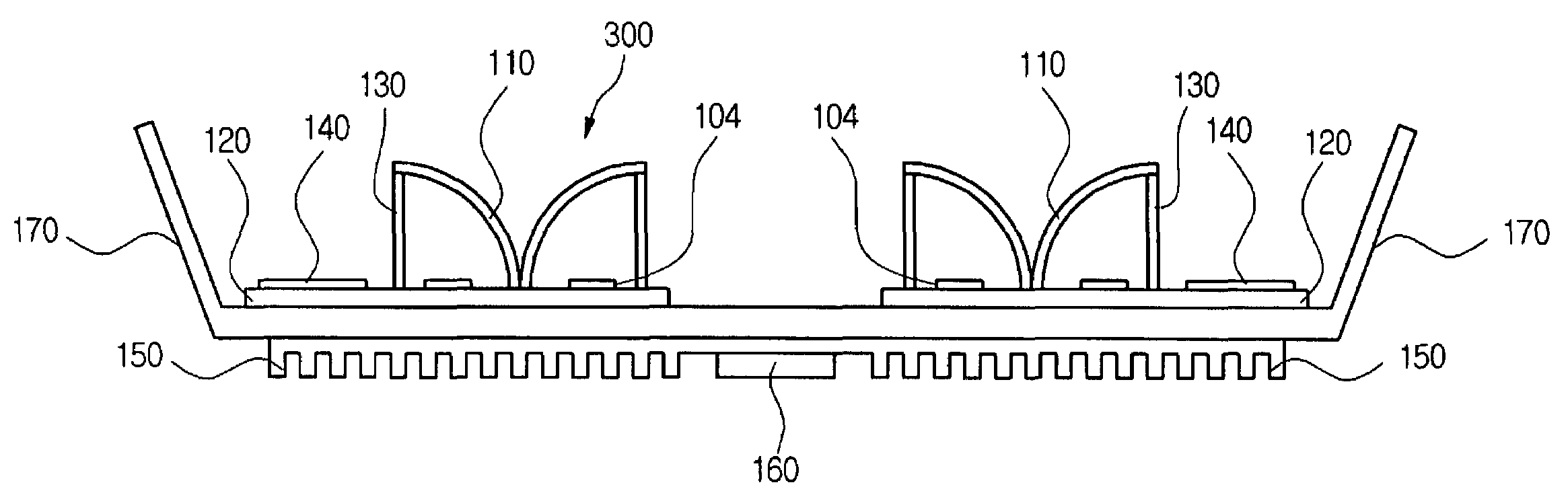
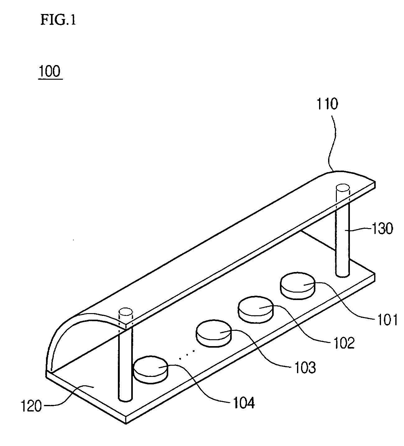
[0024]FIG. 1 is a view conceptually illustrating a light-emitting module according to the present invention.

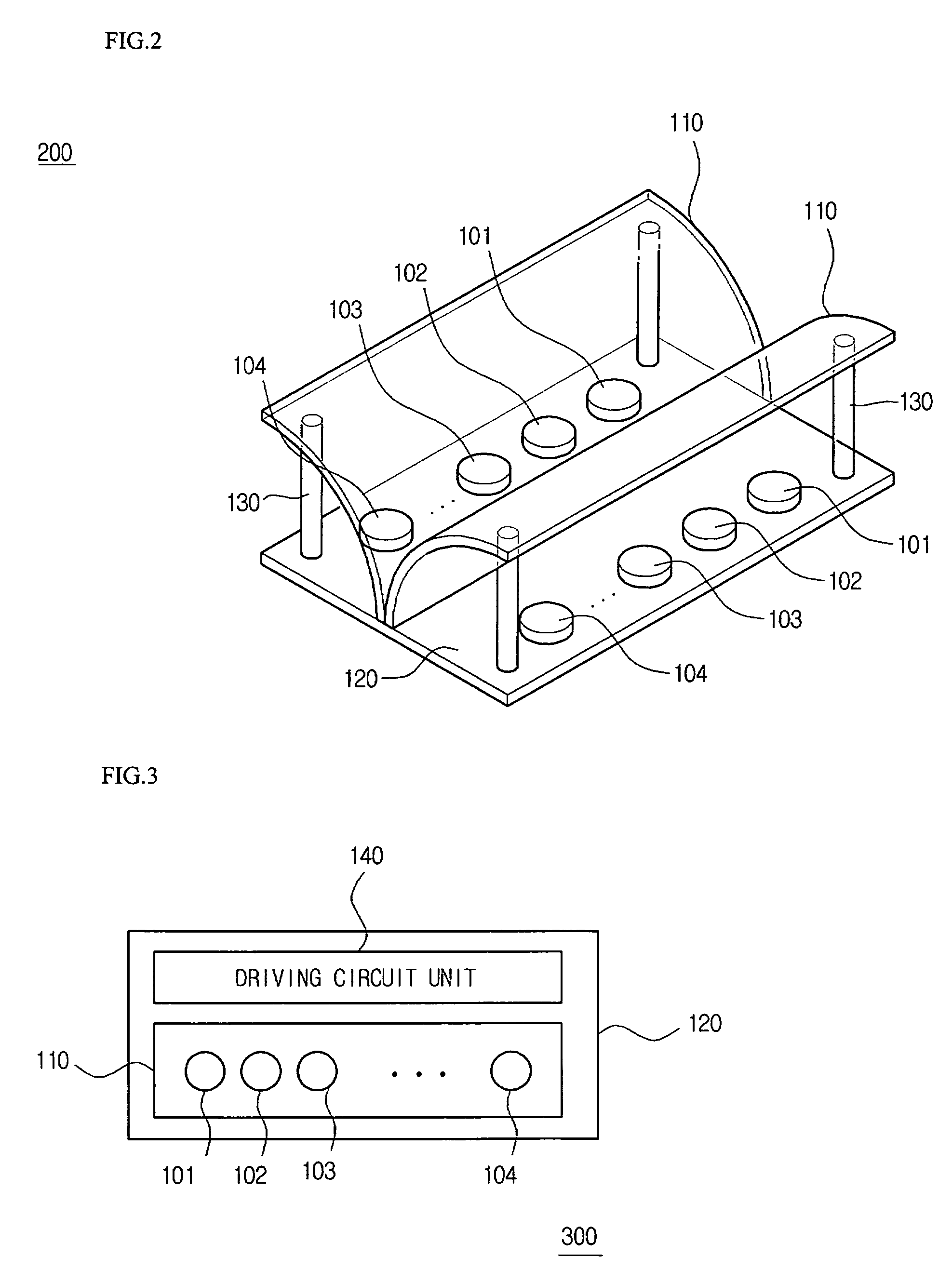
[0025]Referring to FIG. 1, the light-emitting module 100 includes a plurality of light-emitting devices 101, 102, 103, and 104, and a module lens 110. The module lens 110 and the plurality of light-emitting devices 101, 102, 103, and 104 are formed on a printed circuit board (PCB) 120. The PCB 120 may be a metal core PCB (MCPCB).

[0026]The module lens 110 has one side supported by the PCB 120 and the other side supported by a support member 130 formed on the PCB 120.

[0027]According to the present invention, the module lens 110 of an int...


PUM


Abstract

A light-emitting module is provided. The light-emitting module comprises a printed circuit board, a plurality of light-emitting devices, and at least one module lens. The plurality of light-emitting devices are formed on the printed circuit board. At least one module lens is supported by the printed circuit board and reflects light emitted from the plurality of light-emitting devices.

Description

BACKGROUND OF THE INVENTION[0001]1. Field of the Invention[0002]The present invention relates to a light-emitting module and a backlight unit having the same.[0003]2. Description of the Related Art[0004]A light-emitting device used for a light-emitting module is formed of a compound semiconductor. The light-emitting module is widely used for remote controllers of home appliances, and display apparatuses such as display boards. Also, the light-emitting module is also used for a backlight unit of a liquid crystal display (LCD) device.[0005]The LCD device may be also applied to large-sized image apparatuses such as televisions and monitors, and applied to portable apparatuses such as mobile communication terminals.[0006]Particularly, to meet miniaturization and slim profile trends of information telecommunication apparatuses, resistors, condensers, and noise filters, which are parts of the apparatuses, are miniaturized even more, and also the light-emitting device is manufactured in a ...

Claims


Application Information

Patent Timeline
Patent Type & Authority Patents(United States)
IPC IPC(8): G09F13/04F21V7/00F21V7/04F21V19/00F21V23/00F21V29/00F21Y101/02H01L33/58
CPCG02F1/133603H01L25/0753H01L25/167G02F1/133605G02F1/133609G02F2001/133607G02F2001/133612H01L2924/0002H01L33/60H01L2924/00G02F1/133607G02F1/133612G02F1/1335
Inventor PARK, JUN SEOK
Owner SUZHOU LEKIN SEMICON CO LTD
Why Eureka
Try Eureka