Anti-tear protection for smart card transactions

a technology of anti-tear protection and smart card transactions, applied in the field of data/information collection systems and methods, can solve problems such as creating an improper message form

Inactive Publication Date: 2004-04-27
KELLY GUY M +3
View PDF2 Cites 63 Cited by
  • Summary
  • Abstract
  • Description
  • Claims
  • Application Information

AI Technical Summary

Benefits of technology

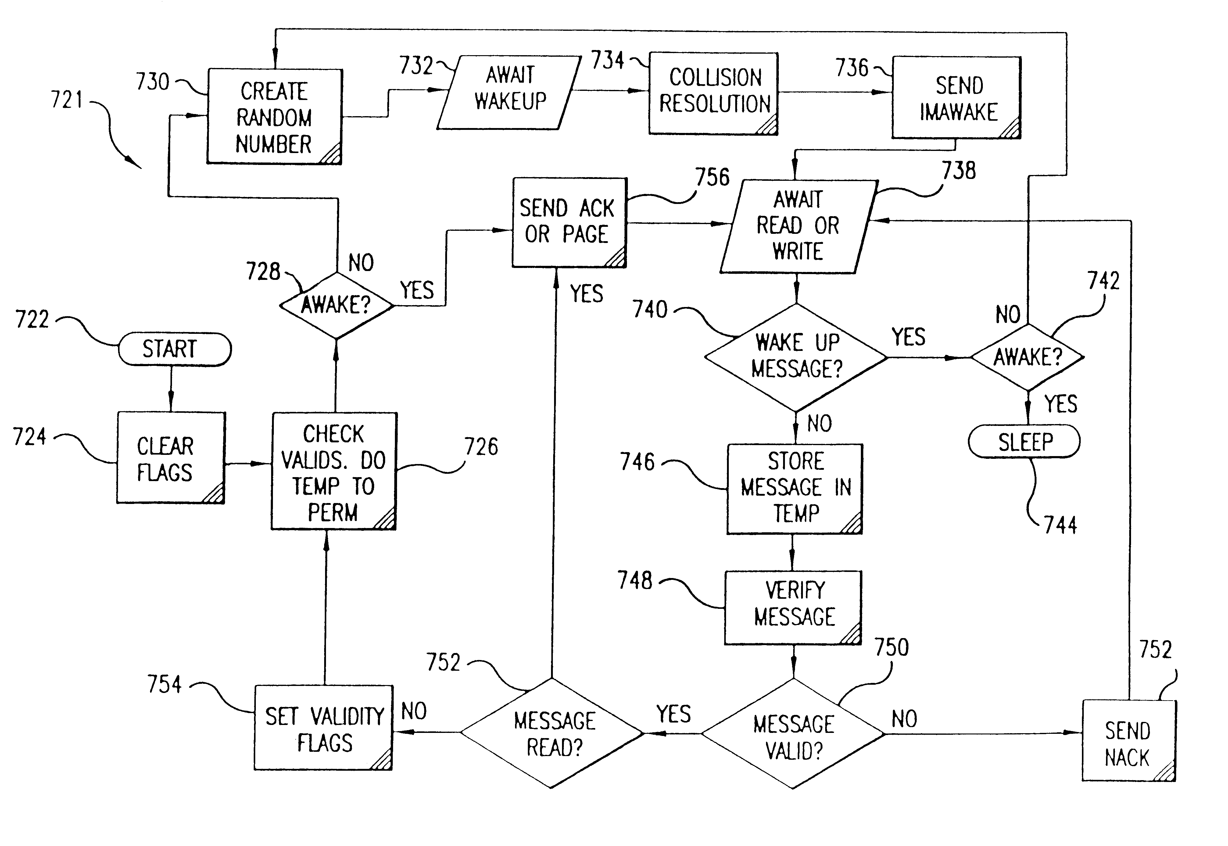
One of the many invention features is collision resolution. In operation, one or more Tags may attempt communication with the Target at the same time. The invention prevents the problem of collisions in communication that occur when two Tags enter the RF field at the same time. Every time a Target receives a first response from a Tag, it checks to see if the response is in proper message form. The first response is designed such that the interference of two or more Tags will likely create an improper message form. Upon receiving an improper message form, the Target will signal the Tags that the message is invalid and the Tags will back-off to retry at a later time. In the rare instance where the Target does not detect a collision when one is present, the Host does a second level of collision detection that is virtually guaranteed to prevent two or more Tags from having access to the same Target at one time.
Another feature of the invention is an improved Tag architecture that reduces the transaction time between the Tag and Target while providing a cost effective Tag with an ultra slim profile and low power requirements. For example, the invention can facilitate complete secure transit transactions in approximately 50 milliseconds (ms), which is approximately 20% of the transaction time generally required by conventional contactless proximity automated data collection systems.
In particular, the invention utilizes serial dataflow techniques and variable speed clocking for the Tag. For example, the invention uses serial, rather than parallel, methods to move data throughout the Tag to realize a significant savings in chip area. In addition, the invention utilizes a dynamic clocking system for the Tag. A low speed clock is used to facilitate communication with the Target. However, for transferring and processing data and messages within the Tag itself, a high speed clock is used.
Moreover, the invention uses one or more Linear Feedback Shift Registers (LFSR) to facilitate Tag functionality. The LFSRs greatly reduce the circuit complexity, thus increasing the speed, flexibility, and reliability of the Tag.
Another significant invention feature is the enhanced design of the Tag data memory. The invention uses ferroelectric random access memory (FRAM) for data storage thus increasing transaction speed, reducing power consumption, and increasing data reliability. For example, the invention performs a write access to a Tag in 1 microsecond (.mu.s) rather than conventional electrically erasable programmable read only memory (EEPROM) based systems, which require approximately 10 ms. Furthermore, the FRAM writing electrical current requirements are considerably less than those of an EEPROM. Additionally, a FRAM typically works for more than 100 billion read or write cycles compared to approximately 1 million in an EEPROM.
Yet another feature of the invention is the Tag analog power protection circuitry. The Tag prevents breakdown (inherent in all silicon chip devices) of the fabricated silicon device from fluctuation in the RF field while permitting the Tag to receive the amplitude modulation (AM) signal from the Target. In particular, the invention features a clamp circuit that is fast enough to react to a switched RF situation and to the AM signal on the RF carrier. The clamp removes the AM voltage fluctuation from the rectified carrier, however, the clamp control signal contains the AM signal, and the control signal can be used as the AM signal for the ASIC receiver circuit.
An additional benefit of this clamping technique is that the clamping voltage can be accurately determined and can be set just below the ASIC breakdown voltage, allowing the ASIC to be produced with smaller geometry and on lower breakdown processes.

Problems solved by technology

The first response is designed such that the interference of two or more Tags will likely create an improper message form.

Method used


Image

  • Anti-tear protection for smart card transactions
  • Anti-tear protection for smart card transactions
  • Anti-tear protection for smart card transactions

Examples


Embodiment Construction

The currently preferred embodiments of the invention are now described with reference to the figures where like reference numbers indicate like elements. Also in the figures, the left most digit of each reference number corresponds to the figure in which the reference number is first used.

While the invention is described in the context of an electronic fare collection system for rapid transit or toll applications, it would be apparent to one skilled in the relevant art that the principles of the invention have considerably broader applicability to other systems in which contactless proximity information / data / message is exchanged, collected, or otherwise used.

The improved Target and Tag of the invention can be used advantageously in a fare collection system similar to that described in International Application Number PCT / US92 / 08892, titled "Non-Contact Automatic Fare Collection System," filed Oct. 19, 1992, WO 93 / 09516, which is incorporated herein by reference in its entirety. Thus...


PUM


Abstract

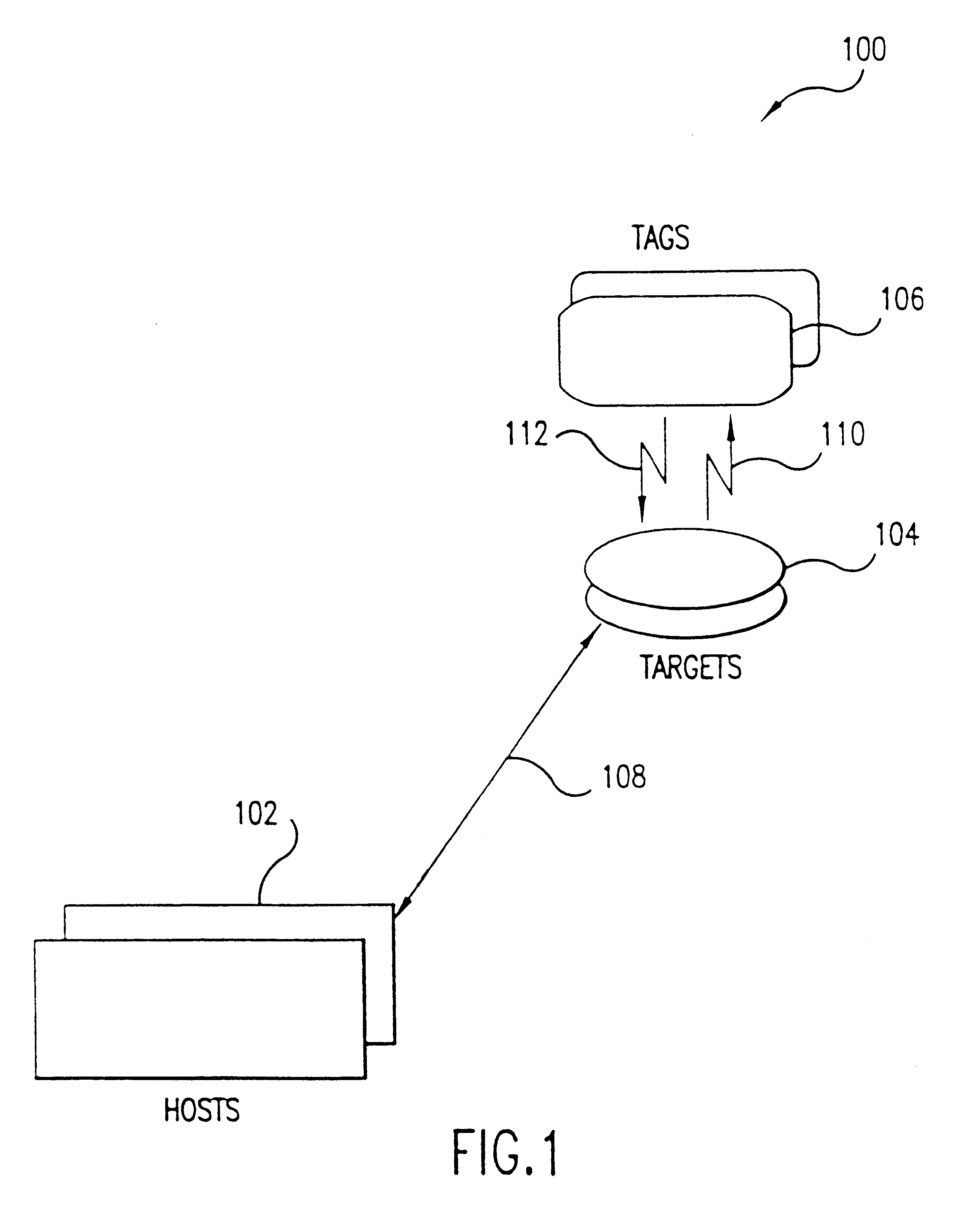
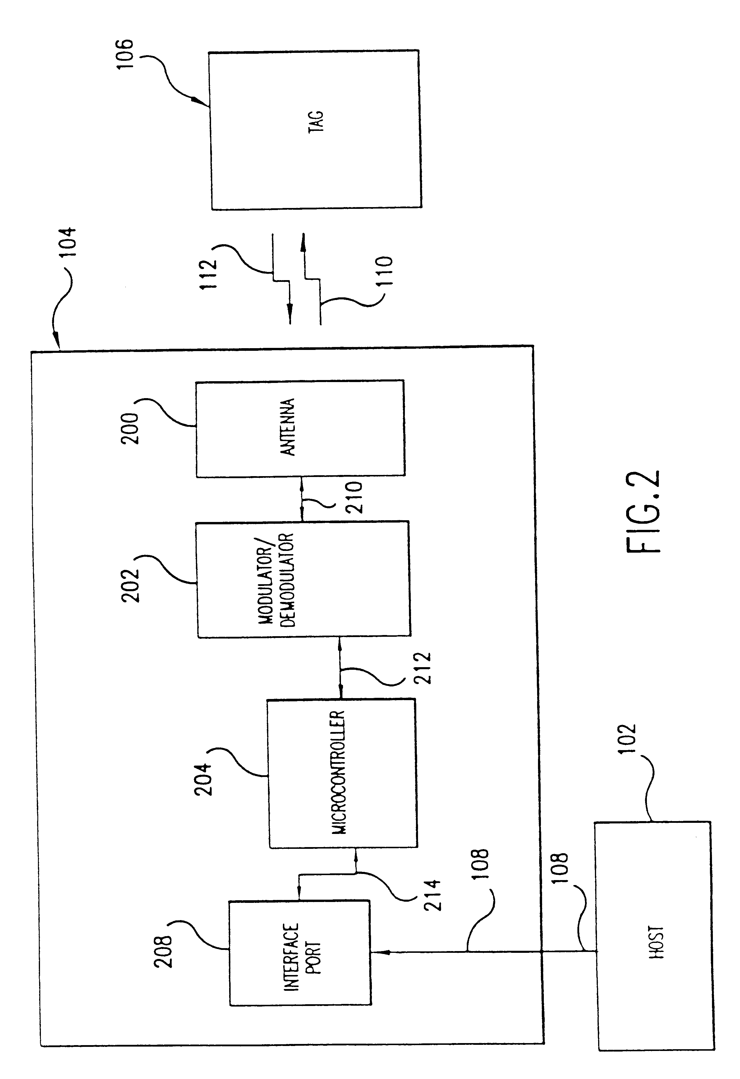
A fast data transfer collection system using message authentication and contactless RF proximity card technology in non-contact storage and retrieval applications. The system is generally comprised of Host computers (application computer systems), Target radio frequency (RF) terminals, and a plurality of portable Tags ("smart" or "proximity" cards). A Host provides specific application functionality to a Tag holder, with a high degree of protection from fraudulent use. A Target provides control of the RF antenna and resolves collisions between multiple Tags in the RF field. A Tag provides reliable, high speed, and well authenticated secure exchanges of data / information with the Host resulting from the use of a custom ASIC design incorporating unique analog and digital circuits, nonvolatile memory, and state logic. Each Tag engages in a transaction with the Target in which a sequence of message exchanges allow data to be read(written) from(to) the Tag. These exchanges establish the RF communication link, resolve communication collisions with other Tags, authenticate both parties in the transaction, rapidly and robustly relay information through the link, and ensure the integrity and incorruptibility of the transaction. The system architecture provides capabilities to ensure the integrity of the data transferred thus eliminating the major problem of corrupting data on the card and in the system. The architecture and protocol are designed to allow simple and efficient integration of the transaction product system into data / information processing installations.

Description

1. Field of the InventionThis invention generally relates to data / information collection systems and methods. More particularly, this invention relates to proximity contactless automated data / information collection systems and methods.2. Description of Related ArtThe number and frequency of fee and / or information based transactions that individuals engage in has increased dramatically over the years. As a result of this increase in transactions, the amount of paper produced and time spent engaging in and processing these transactions has also increased. Proximity card technology has been used effectively to reduce waste by eliminating the need for paper or plastic in some transactions and to increase efficiency of these transactions by reducing the time spent engaging in and processing these transactions.Proximity card technology can be advantageously utilized in a wide variety of applications. One significant application concerns replacing small ticket / cash transactions. Worldwide,...

Claims


Application Information

Patent Timeline
Patent Type & Authority Patents(United States)
IPC IPC(8): G06K7/00G06F21/60G06F12/14G06F21/62G06K17/00G06K19/07G06K19/073H04B5/02
CPCG06K7/0008G06K7/10059G06K19/0701G06K19/0723
Inventor KELLY, GUY M.PAGE, KEVIN J.PLUM, DON P.RAVENIS, II, JOSEPH V J
Owner KELLY GUY M
Why Eureka
Try Eureka