Tubular fiber structure and fiber reinforced composite material

a technology of tubular fiber which is applied in the field of tubular fiber structure and fiber reinforced composite material, can solve the problems of reducing the strength, reducing slit cracks, so as to reduce the energy absorption efficiency, reduce the strength, and simplify the coupling structure

Inactive Publication Date: 2015-10-22
TOYOTA IND CORP
View PDF13 Cites 9 Cited by
  • Summary
  • Abstract
  • Description
  • Claims
  • Application Information

AI Technical Summary

Benefits of technology

[0009]When applying the structure of patent document 1 to an energy absorption member, the coupling of the energy absorption member to the bumper beam 81 and the frame body 83 at the flanges simplifies the coupling structure. However, in the structure of patent document 1, the slits are cut into the two ends of the tube, which is formed by a three-axis braid texture, and the cut ends are bent to form the flanges. Thus, when using the structure of patent document 1 as a reinforcement for fiber-reinforced plastic to form the energy absorption member, cracks may form from the slits and lower the energy absorption efficiency. Further, when increasing the amount of the axial threads to counter compression in the three-axis braid texture, undulations (crimps) increase in the radial threads. This lowers the strength.
[0013]In this structure, the tubular fiber structure includes the flange that is shaped at the region of the end of the rolled fabric base material. Thus, the formation of cracks from the boundary of the flange and the tube is limited when forming a composite material. This differs from when cutting slits into the region at the end of a tubular braid texture. Further, the tubular fiber structure is entirely formed by a fabric base material. Thus, compared to when threads serving as reinforcement fibers of a tube are free, the threads may be laid out in an orderly manner when manufacturing a composite material. Accordingly, when the tubular fiber structure, which includes the flange, is used as a reinforcement for a tubular fiber reinforced composite material that can easily be coupled to another member, the necessary strength may be ensured.

Problems solved by technology

Thus, when using the structure of patent document 1 as a reinforcement for fiber-reinforced plastic to form the energy absorption member, cracks may form from the slits and lower the energy absorption efficiency.
This lowers the strength.
This results in a complicated manufacturing process.
Thus, when manufacturing a composite material, it is difficult to lay out the threads, and it is difficult to increase the strength.

Method used


Image

  • Tubular fiber structure and fiber reinforced composite material
  • Tubular fiber structure and fiber reinforced composite material
  • Tubular fiber structure and fiber reinforced composite material

Examples


first embodiment

[0043]A first embodiment of a tubular fiber structure will now be described with reference to FIGS. 1 to 4.

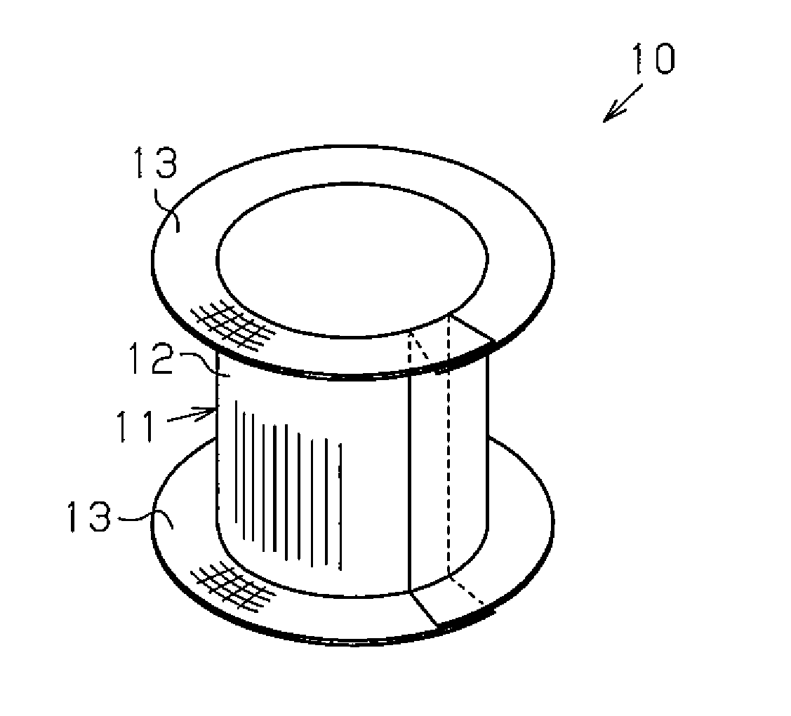
[0044]Referring to FIG. 1, a tubular fiber structure 10 is formed by rolling a sheet of a fabric base material 11 and shaping the rolled fabric base material 11. The tubular fiber structure 10 includes a tube 12 and a flange 13, which is located on at least one side (i.e., one axial end) of the tube 12. In this embodiment, the tube 12, which is tubular and has a circular cross-section, includes the flange 13 at two sides (two axial ends). The “fabric base material” is formed by threads laid out to extend in at least two directions and includes at least a portion that is woven from threads (interweaved portion).

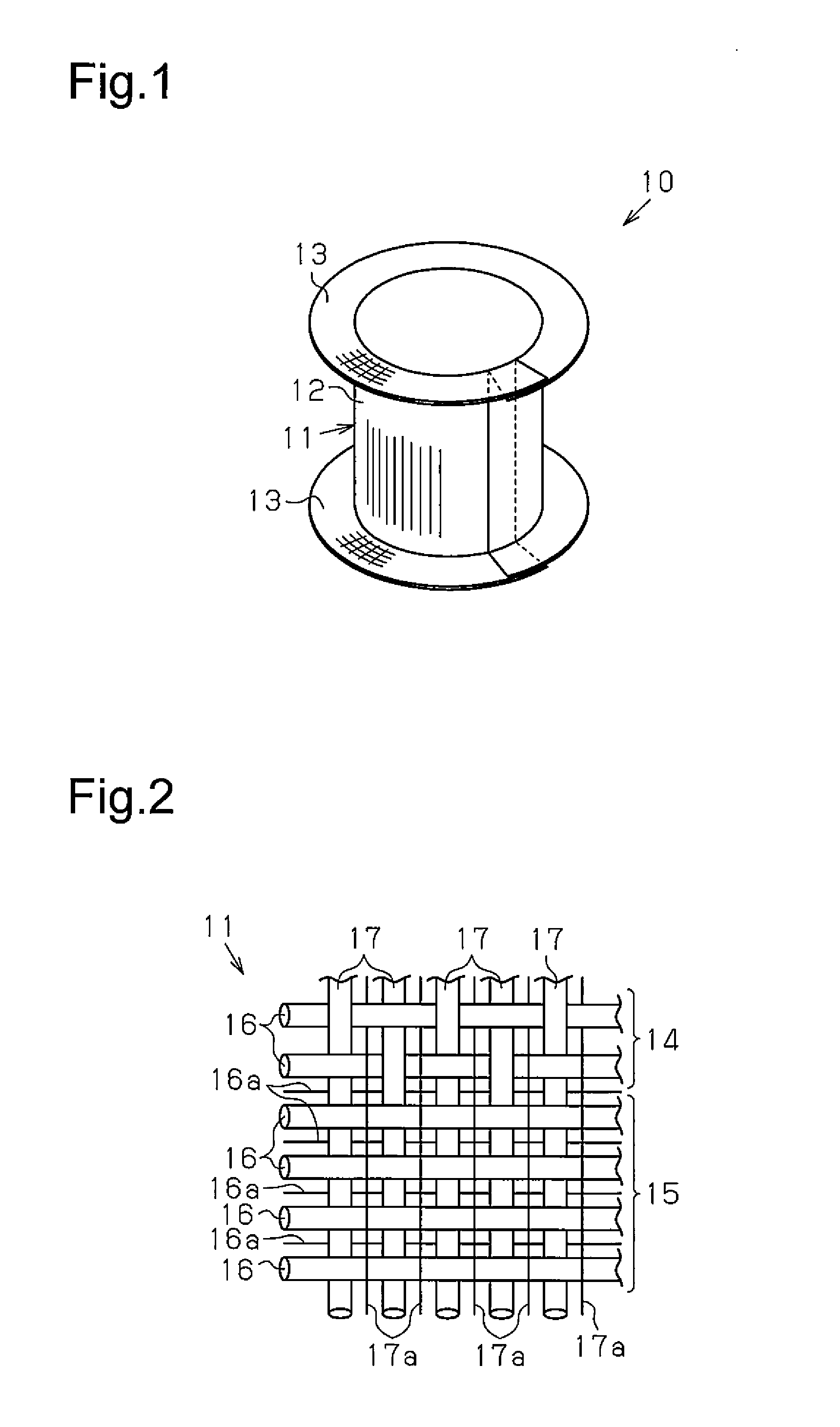
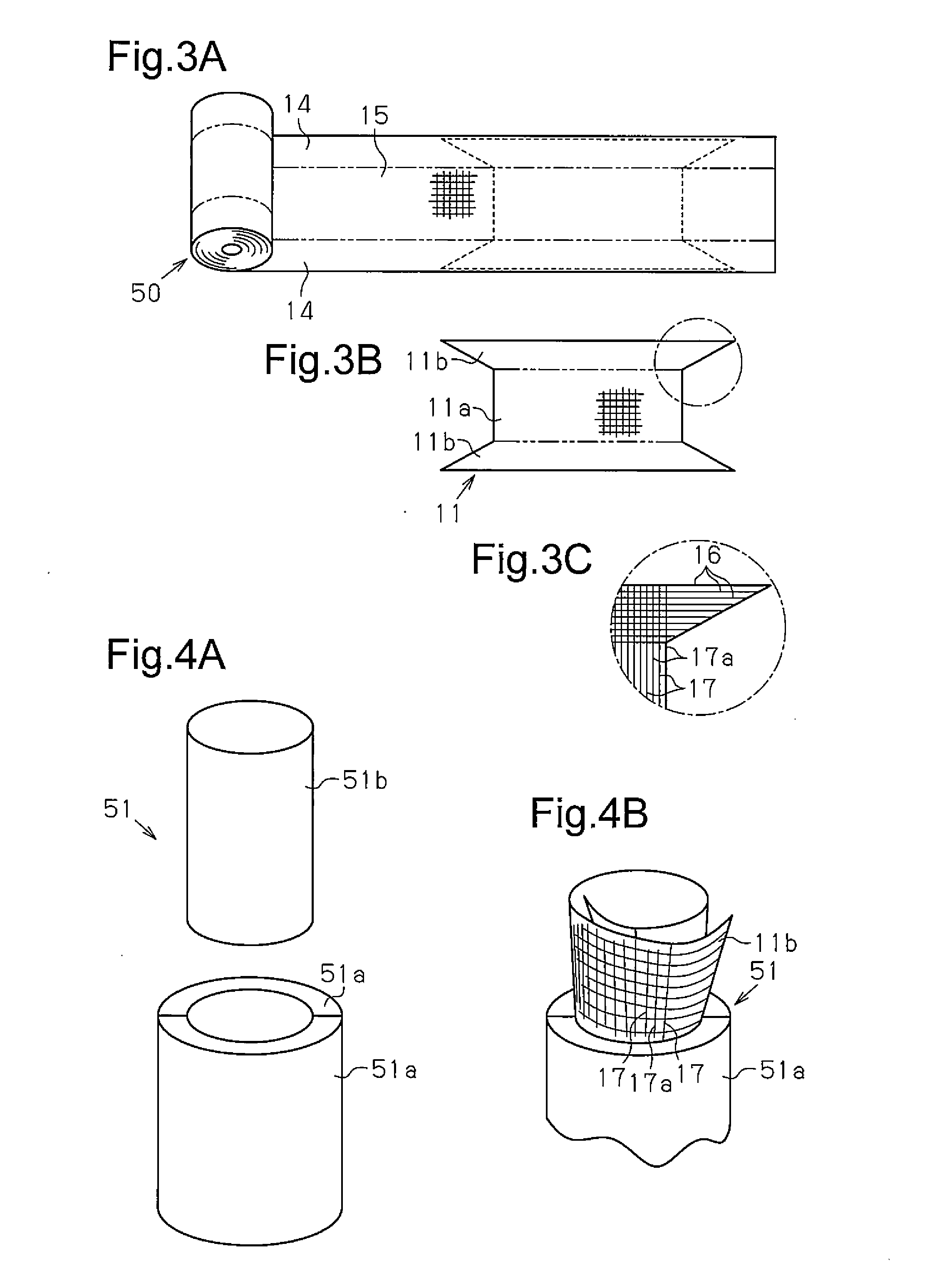
[0045]Referring to FIG. 2, the fabric base material 11 includes a woven texture 14 and a non-woven texture 15. As shown in FIG. 3A, the fabric base material 11 of this embodiment includes the woven texture 14 at the two widthwise sides of the fabric base material 11 and t...

second embodiment

[0061]A second embodiment will now be described with reference to FIGS. 5 to 7. This embodiment differs from the tubular fiber structure 10 of the first embodiment in that a reinforcement portion 18 formed by a fabric base material 21 is arranged at the inner side of the tube 12. Otherwise, the structure is basically the same as the tubular fiber structure 10 of the first embodiment. Same reference numerals are given to those components that are the same as the corresponding components of the first embodiment. Such components will not be described in detail.

[0062]As shown in FIG. 5, the fabric base material 21 of the reinforcement portion 18 is continuous with a rolled inner end 11d of the tube-corresponding portion 11a, which corresponds to the tube 12, in the fabric base material 11 forming the tube 12 and the flanges 13. The fabric base material 21 is arranged so as to extend in the radial direction of the tube 12. The fabric base material 21 includes a fixed portion 21a, which i...

third embodiment

[0070]A third embodiment will now be described with reference to FIGS. 8 to 10. This embodiment differs from the first embodiment in that multiple layers of the fabric base material 11 are stacked and sewn together with stitching threads 22 so that the tube 12 is three-dimensional. Same reference numerals are given to those components that are the same as the corresponding components of the first embodiment. Such components will not be described in detail.

[0071]As shown in FIGS. 8 and 9, the overlapping layers of the fabric base material 11 at the tube 12 are lock-stitched with the stitching threads 22 so that the tubular fiber structure 10 is three-dimensional. As shown in FIG. 9, the stitching threads 22 include a piercing thread 22a, which is pierced through and returned from portions where the fabric base material 11 is overlapped in layers, and a locking thread 22b, which locks the piercing thread 22a to the fabric base material 11 at portions of the fabric base material 11 whe...


PUM

PropertyMeasurementUnit
anglesaaaaaaaaaa
anglesaaaaaaaaaa
anglesaaaaaaaaaa

Abstract

A tubular fiber structure, which includes a tubular section and a flange section that is on at least one end of the tubular section and which is formed by shaping a wound fabric base material.

Description

CROSS REFERENCE TO RELATED APPLICATIONS[0001]This application is a National Stage of International Application No. PCT / JP2013 / 078764, filed Oct. 24, 2013, claiming priority based on Japanese Patent Application No. 2012-261056, filed Nov. 29, 2012, the contents of all of which are incorporated herein by reference in their entirety.FIELD OF THE INVENTION[0002]The technology of the present disclosure relates to a tubular fiber structure and a fiber reinforced composite material that uses the tubular fiber structure as a reinforcement.BACKGROUND OF THE INVENTION[0003]A typical automobile includes bumpers secured to the front and rear of the vehicle body to absorb impact energy of a collision and protect the vehicle body and the vehicle occupants during a collision. A bumper needs to absorb, in an irreversible manner, the energy of the load that is produced when the automobile collides with an obstacle. There are structures that support the bumper with a substantially tubular energy abso...

Claims


Application Information

Patent Timeline
Patent Type & Authority Applications(United States)
IPC IPC(8): D03D3/02
CPCD03D3/02B60R19/03D03D1/00D10B2505/02B32B1/08D03D13/004B32B5/022B32B5/024B32B5/06B32B5/22B32B5/26B32B2250/20B32B2260/021B32B2260/046B32B2262/02B32B2262/0269B32B2262/10B32B2262/101B32B2262/103B32B2262/105B32B2262/106B32B2307/50B32B2307/56B32B2597/00B32B2605/00
Inventor HORI, FUJIOKAMIYA, RYUTA
Owner TOYOTA IND CORP
Why Eureka
Try Eureka