Dielectric waveguide filter

A dielectric waveguide and filter technology, applied in the field of dielectric waveguide filters, can solve the problems of high process requirements, high cost, complex coupling structure, etc., and achieve the effect of low process requirements, low cost, and simple coupling structure

Active Publication Date: 2017-04-19
SHENZHEN SAMSUNG COMM TECH RES +1
View PDF8 Cites 10 Cited by
  • Summary
  • Abstract
  • Description
  • Claims
  • Application Information

AI Technical Summary

Problems solved by technology

[0004] However, the inventors found that this method requires the cooperation of the threaded part (tuning screw sleeve 6 or coupling screw sleeve 10), the debugging screw 8 and the nut (tuning nut 7 or coupling nut 9), which makes the coupling structure complex, resulting in relatively high process requirements and costs. high

Method used


Image

  • Dielectric waveguide filter
  • Dielectric waveguide filter

Examples


Embodiment Construction

[0018] In order to make the object, technical solution and advantages of the present invention clearer, the present invention will be further described in detail below in conjunction with the accompanying drawings.

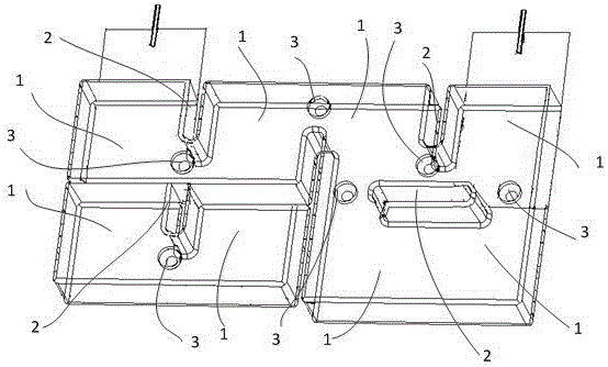
[0019] Such as figure 2 As shown, it is a dielectric waveguide filter provided in the embodiment of the present invention. The dielectric waveguide filter includes a plurality of interconnected resonators 1, and coupling windows 2 and coupling holes are formed between adjacent resonators 1. 3; among them,

[0020] Each coupling window 2 is a hollow cavity structure, and the inner wall of each coupling window 2 is coated with a first metallized coating for electromagnetic shielding;

[0021] Each coupling hole 3 is a blind hole arranged close to the corresponding coupling window 2, and the inner wall of each coupling hole 3 is coated with a second metallized coating for electromagnetic shielding;

[0022] The coupling amount of the dielectric waveguide filter ca...


PUM


Abstract

The invention provides a dielectric waveguide filter comprising a plurality of resonators mutually connected. Coupling windows and coupling holes are formed between adjacent resonators. Each coupling window has a cavity structure; the inner wall of each coupling window is coated with a first metalized plating layer for electromagnetic shielding; each coupling hole is a blind hole approaching the corresponding coupling window; and the inner wall of each coupling hole is coated with a second metalized plating layer for electromagnetic shielding. The coupling value of the dielectric waveguide filter can be adjusted by grinding the corresponding metalized plating layer of any coupling window or any coupling hole. The dielectric waveguide filter has advantages of simple coupling structure, low process requirement, and low cost.

Description

technical field [0001] The invention relates to the technical field of electrical components used in the communication industry, in particular to a dielectric waveguide filter. Background technique [0002] In communication systems, waveguide filters are usually used to filter out interference signals or clutter signals within a specific frequency range. The traditional waveguide filter structure is a metal cavity structure, that is, precious materials such as metal or metal alloys (such as aluminum, magnesium alloy, etc.) are used to hollow out the middle or part of the structure. The metal material mainly plays the role of electromagnetic shielding and structural support, while Although the waveguide filter designed in this way has a high Q value, its volume and weight are large, which is not conducive to installation, disassembly and transportation, and the price of precious metals is high, resulting in high cost of the waveguide filter. [0003] In order to solve the de...

Claims


Application Information

Patent Timeline
Patent Type & Authority Applications(China)
IPC IPC(8): H01P1/20
CPCH01P1/2002
Inventor 康海聚蔡磊
Owner SHENZHEN SAMSUNG COMM TECH RES
Why Eureka
Try Eureka