
Printing methods and apparatus

a printing method and printing method technology, applied in printing, typewriters, electrical devices, etc., can solve the problems of reducing quality, reducing the time for ripping, and reducing the quality of the paper, and achieve the effect of high quality

Inactive Publication Date: 2009-06-04
EPIC PRODS INT CORP
View PDF17 Cites 17 Cited by
  • Summary
  • Abstract
  • Description
  • Claims
  • Application Information

AI Technical Summary

Problems solved by technology

However, the quality diminishes as printing speed increases (i.e., the speed of the sheets past the printing head), so high-quality printing on commercially affordable printers can be achieved only at production rates that are less than optimum.
For a large print job, it generally takes considerable time for the RIP to be performed, thus seriously delaying the printing operation which itself might require only a fraction of the time required for the RIP.
This has adverse impact on a company's ability to earn profit and maximize shop throughput.
However, since the printing of a page is typically performed more quickly than the RIP, the printing will “catch up” to the RIP, thereby delaying the final printing until the RIP has been finished.

Method used


Image

  • Printing methods and apparatus
  • Printing methods and apparatus
  • Printing methods and apparatus

Examples


Embodiment Construction

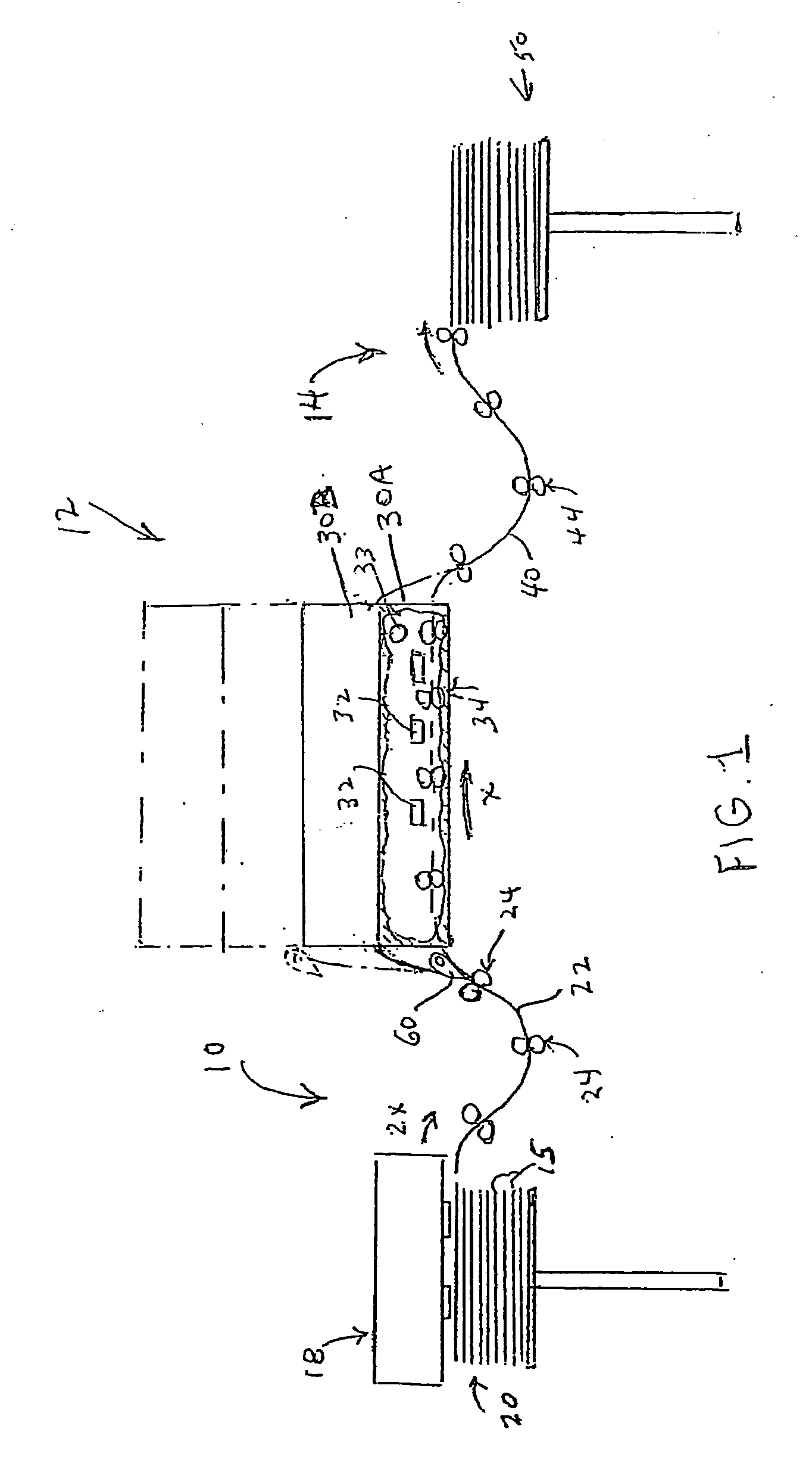
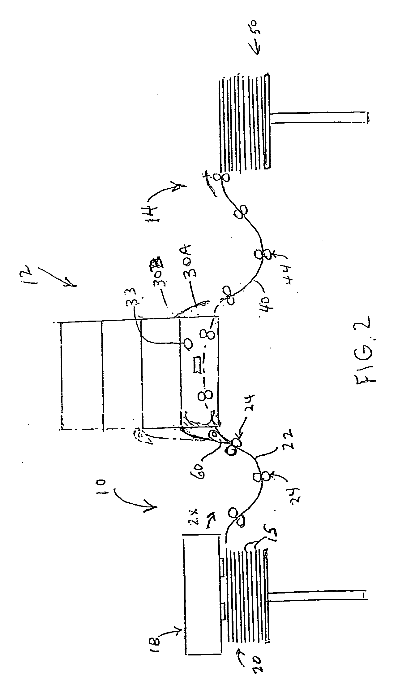
[0013]Depicted in FIG. 1 is a printing apparatus comprising a sheet infeed section 10, a printing section 12, and a sheet outfeed section 14. The sheet infeed section 12 comprises a feed mechanism 18 which can be any suitable conventional high-speed sheet feeder capable of feeding printable sheets 15, such as blank paper sheets, sequentially from a preferably vertical stack 20 of sheets (e.g., see U.S. Pat. No. 6,095,513, disclosing a high-speed sheet feeder). The sheets are fed onto an infeed path 22 at a feed speed and are advanced along that path by a conventional advancing mechanism such as roller pairs 24 in which one roller of each pair is driven by a motor. One or more stacks could feed into the feed path.

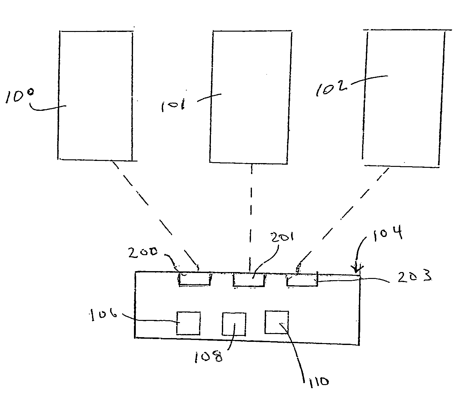
[0014]The printing section 12 comprises a plurality of printing units. Any type of printing units can be used and they can be disposed in any suitable arrangement. However, it is preferable to use vertically-stacked, digital, inkjet printing units, which are desirably of ide...


PUM


Abstract

The identical printing of a stack of sheets (e.g., paper) is performed by vertically stacked inkjet printing units, each of which prints sheets at a printing speed. All sheets are fed from a stack along an infeed path at a feeding speed which is faster than the printing speed. The sheets are sequentially introduced into the respective printing heads, e.g., by the actuation of a gate mechanism disposed in the infeed path. After the sheets have been printed in the printing units at the slower printing speed, and after the print medium has been fixed, the sheets are discharged from the printing units and fed along a common outfeed path at the higher feeding speed. For variable-data printing, raster image processing is performed by assigned separate RIP computer units to process respective batches of the pages of the printing job.

Description

[0001]This application claims the benefit of the Nov. 13, 2007 filing date of Provisional Application No. 60 / 996,349.BACKGROUND OF THE INVENTION[0002]The invention relates to a printing apparatus and method.[0003]Inkjet printing is highly favored due to its ability to produce high-quality printing. However, the quality diminishes as printing speed increases (i.e., the speed of the sheets past the printing head), so high-quality printing on commercially affordable printers can be achieved only at production rates that are less than optimum.[0004]It would thus be desirable to provide a printing method and apparatus, preferably but not necessarily employing inkjet printing, which attains higher production rates without sacrificing quality.[0005]Another shortcoming in the printing field involves large variable-data print jobs, i.e., where a large number of sheets are to be printed with different images on most or all sheets. Current digital printing systems for performing such variable-...

Claims


Application Information

Patent Timeline
Patent Type & Authority Applications(United States)
IPC IPC(8): H04N1/034B41J2/01
CPCB41J3/54B41J13/0009B41J11/002B41J3/543
Inventor DAHLGREN, MAX W.
Owner EPIC PRODS INT CORP
Learn More