Multiview and multiangle image reconstruction device

a multi-angle image and reconstruction device technology, applied in the direction of mirrors, instruments, mountings, etc., can solve the problems of difficult to project an image over a substantial distance, glasses must be placed, and the distance is very short, so as to achieve the effect of free adjustment of the quality and the distance of the projected imag

Inactive Publication Date: 2009-06-04
CHOI KYUNG GUN +1
View PDF4 Cites 2 Cited by
  • Summary
  • Abstract
  • Description
  • Claims
  • Application Information

AI Technical Summary

Benefits of technology

[0011]Accordingly, the present invention has been made in an effort to solve the problems occurring in the related art, and an object of the present invention is to provide an image reconstruction device which allows a projected image to be viewed from various directions.
[0012]Another object of the present invention is to provide an image reconstruction device in which a support plate for supporting an object can be moved upward and downward so that the size of a 3D image to be reconstructed can be enlarged or reduced.
[0013]Still another object of the present invention is to provide an image reconstruction device which allows the quality and the distance of a projected image to be freely adjusted.

Problems solved by technology

Among these systems, while the lenticular lens system and the shutter glass system can project an image to a predetermined distance, they have a problem in that the distance is very short and glasses must be put on to view the image.
Further, while the parallax barrier system does not employ glasses, it has a problem in that a projection distance is so short that it is difficult to project an image over a substantial distance.
In the volumetric 3D display system, while an image can be viewed through 360°, it has a drawback in that the size of a stereoscopic image depends on the size of a rotating screen wing and the image is not clear.
However, since a hologram is formed by putting, on a film, wave lengths reflected from an object, the image cannot be projected outside the film.
In addition, while the system, which employs the focal distance of a lens or a mirror, has a simple theory, it is difficult to actually realize the system.
This is because a substantial amount of an image is distorted or removed by the lens or the mirror.
Therefore, while the system can be manufactured using a simple principle, when actually observing the image by the eyes, it is impossible to view the image at multiple viewing points, and an unclear and dim image can be provided at a specific viewing point to cause fatigue to the eyes.
Nevertheless, the conventional image reconstruction device has a defect in that the object 50 can be viewed from only one angle and the side face and the rear face of the object cannot be viewed.

Method used


Image

  • Multiview and multiangle image reconstruction device
  • Multiview and multiangle image reconstruction device
  • Multiview and multiangle image reconstruction device

Examples


Embodiment Construction

[0023]Reference will now be made in greater detail to a preferred embodiment of the invention, an example of which is illustrated in the accompanying drawings. Wherever possible, the same reference numerals will be used throughout the drawings and the description to refer to the same or like parts.

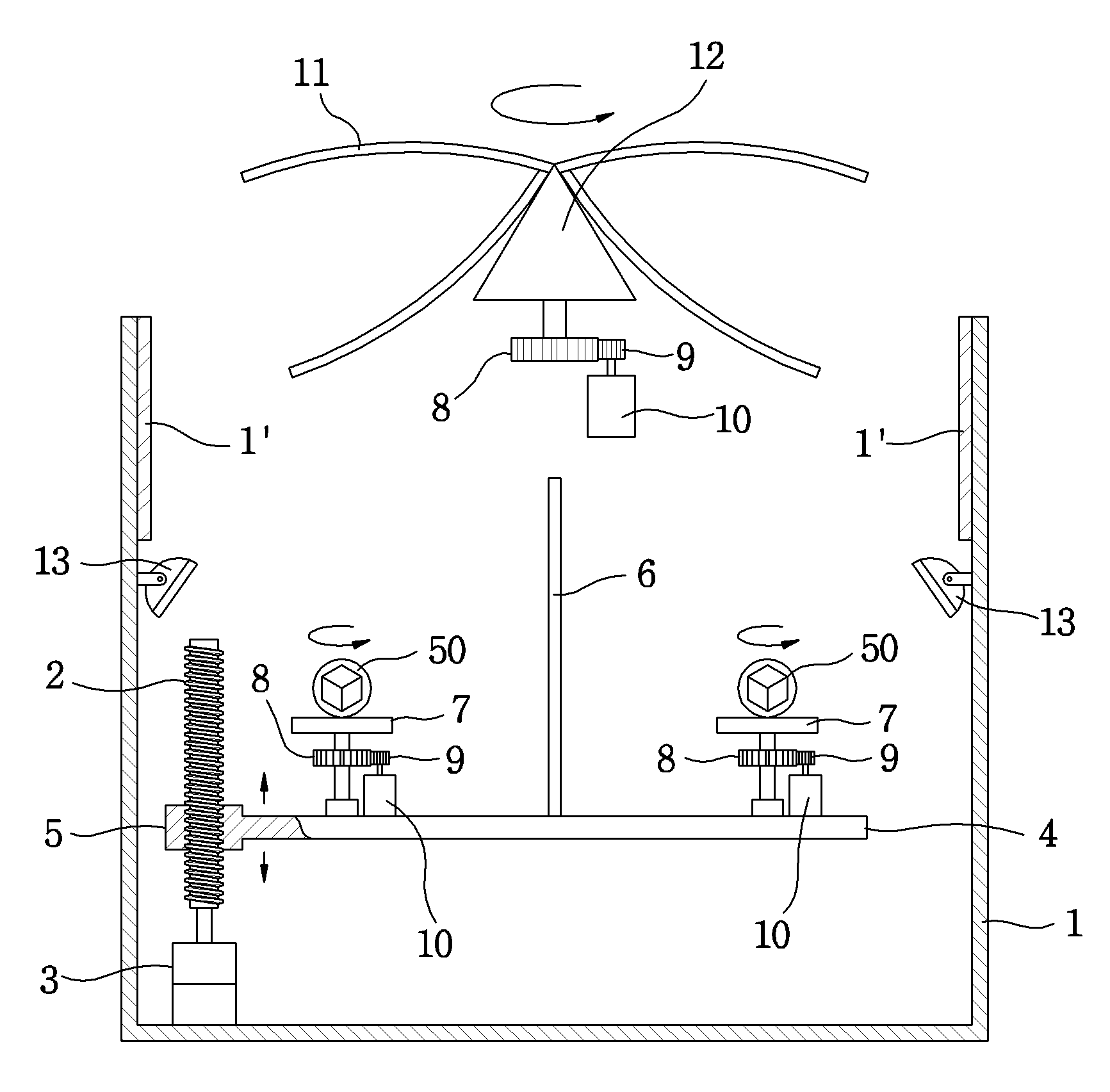
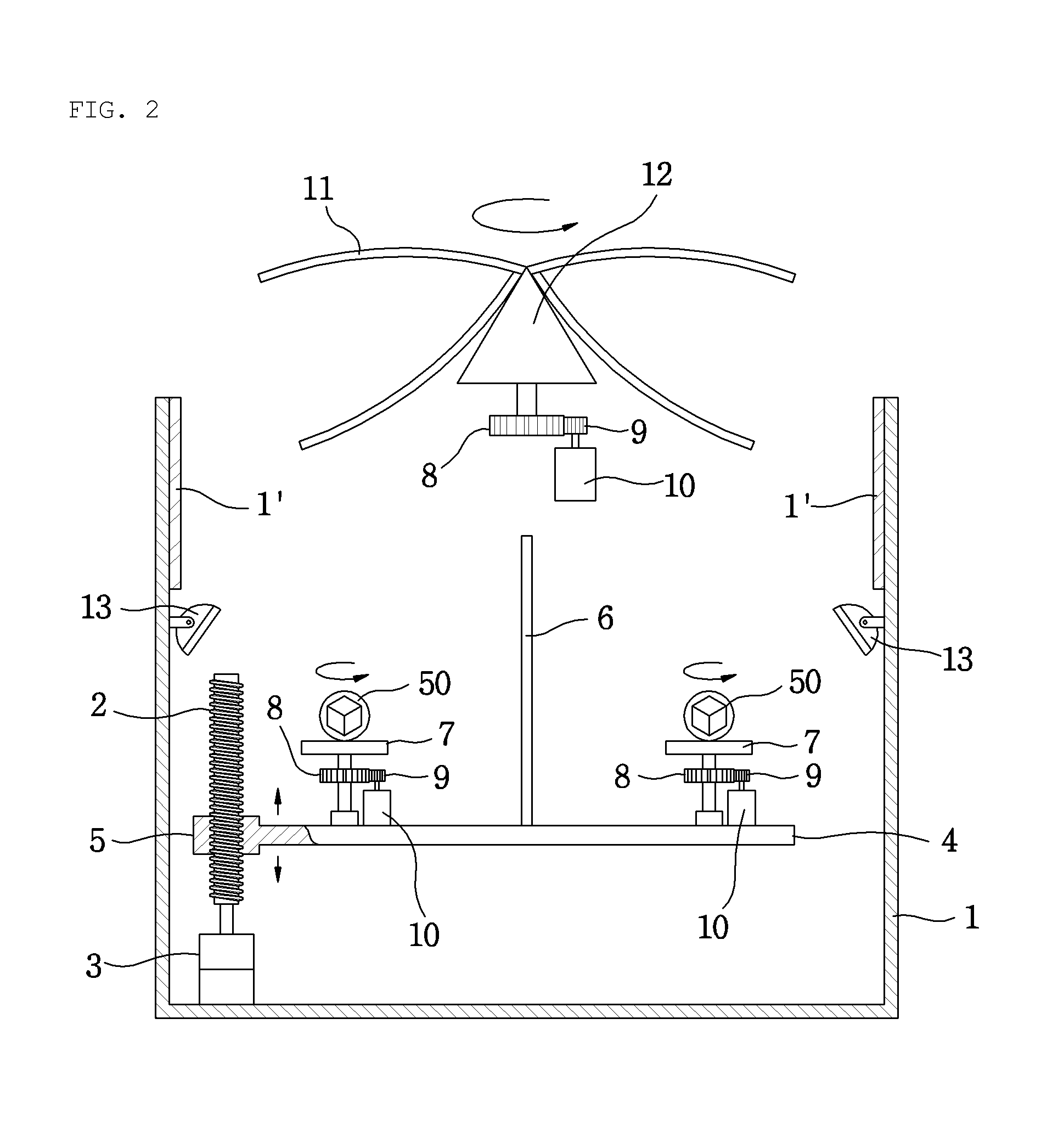
[0024]FIGS. 2 and 3 illustrate a multiview and multiangle image reconstruction device in accordance with an embodiment of the present invention, wherein FIG. 2 is a schematic cross-sectional view and FIG. 3 is a plan view of FIG. 2.

[0025]The image reconstruction device shown in FIGS. 2 and 3 has a housing 1 which is opened at the upper end thereof. A support plate 4 is arranged adjacent to the lower end of the housing 1, and a plurality of partition walls 6 are installed on the support plate 4 to divide the area on the support plates 4 into parts. A plurality of rotation plates 7 are rotatably installed on the support plate 4.

[0026]Below each rotation plate 7, there are disposed a driven g...


PUM


Abstract

An image reconstruction device includes a housing which is opened at an upper end thereof, a support plate which is arranged adjacent to a lower end of the housing, a plurality of partition walls which divide an area on the support plate into parts, rotation plates which are installed on the support plate to allow objects to be placed thereon, illuminators which are mounted to a side wall of the housing, reflection mirrors which are positioned above the illuminators, and a pair of concave mirrors which are arranged in an upper part of the housing. The pair of concave mirrors are provided in each of four directions, and these four pairs of concave mirrors are rotated above the housing by concave mirror rotation means.

Description

BACKGROUND OF THE INVENTION[0001]1. Field of the Invention[0002]The present invention relates to a multiview and multiangle image reconstruction device which allows a stereoscopic 3D (three-dimensional) image to be obtained.[0003]2. Description of the Related Art[0004]A stereoscopic image represents a virtual image which is realized in a 3D space, and can be obtained through various methods. In one method, an image is divided into left and right parts so that the left and right parts can be respectively viewed by left and right eyes. This method includes a lenticular lens system, a shutter glass system, and a parallax barrier system. Among these systems, while the lenticular lens system and the shutter glass system can project an image to a predetermined distance, they have a problem in that the distance is very short and glasses must be put on to view the image. Further, while the parallax barrier system does not employ glasses, it has a problem in that a projection distance is so ...

Claims


Application Information

Patent Timeline
Patent Type & Authority Applications(United States)
IPC IPC(8): G02B7/182
CPCG02B27/2292F21S10/06G02B30/56
Inventor CHOI, KYUNG GUNHAHN, KYEONG HO
Owner CHOI KYUNG GUN
Why Eureka
Try Eureka