Scrubber tower of a flue gas purification device

a technology of flue gas purification and scrubber tower, which is applied in the direction of distillation separation, separation machines, mixing methods, etc., can solve the problems that gas purification does not meet the corresponding economical and ecological demands any more, and achieve the effect of enlarging or reducing the size of means/inserts, enlarging or reducing the size of adjacent construction elements

Inactive Publication Date: 2017-12-07
DOOSAN LENTJES GMBH
View PDF0 Cites 0 Cited by
  • Summary
  • Abstract
  • Description
  • Claims
  • Application Information

AI Technical Summary

Benefits of technology

[0047]This embodiment corresponds to example B with the proviso that the upper layer / tray T3 is made floatable onto a liquid bath (provided in / above the contact zone) by filling air into said bars. By sucking off air and / or increasing the mass of the bars / tray T3 this tray will plunge into said liquid bath and correspondingly approach the other tray T4 arranged beneath, thereby varying the size of the flow through openings of the tray T4. By reducing the weight of the bars / tray and / or by introducing air into the bars of tray T3 the distance between the two adjacent trays may be enlarged again when tray T3 ascents again.
[0051]In other words, the cross section of one or more flow-through openings is adjusted by enlarging or reducing the size of means / inserts placed within or adjacent to these openings. The same effect is possible by enlarging or reducing the size of construction elements adjacent to the flow through openings.
[0053]The package (tray installation) can be subdivided into compartments, which are arranged in a horizontal fashion to allow sectional variations and to increase the homogeneity of the liquid bath.

Problems solved by technology

As a consequence the gas purification does not fulfil the corresponding economical and ecological demands any more.

Method used


Image

  • Scrubber tower of a flue gas purification device
  • Scrubber tower of a flue gas purification device
  • Scrubber tower of a flue gas purification device

Examples


Embodiment Construction

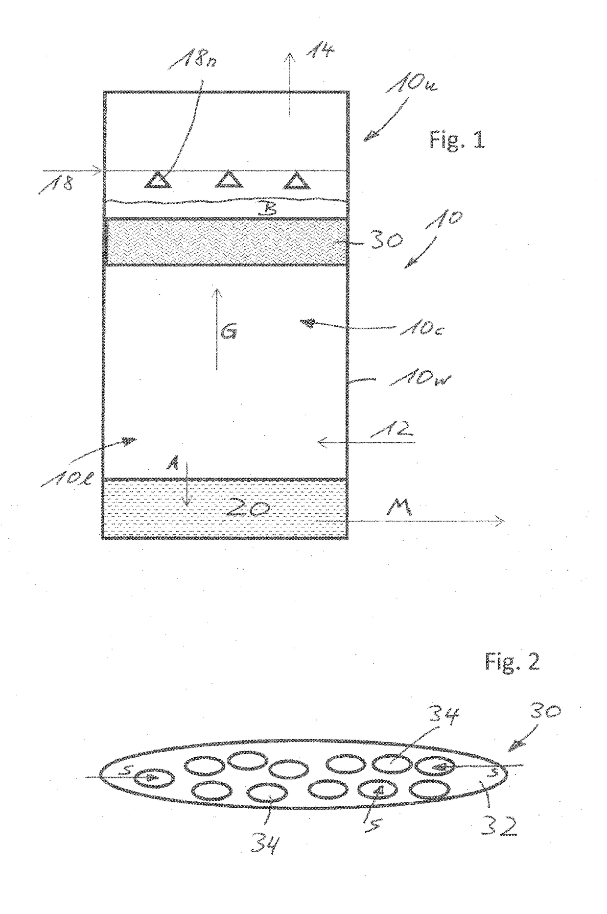
[0065]FIG. 1 represents the main features of a scrubber tower 10 by which a flue gas from an associated power station (not illustrated) will be purified.

[0066]Scrubber tower 10 comprises a cylindrical outer wall 10w, a flue gas entrance 12 at a lower part 10l and a flue gas exit 14 at an upper part 10u, a liquid (seawater) entrance 18 at said upper part 10u and a liquid exit 20 at said lower part 10l. Said liquid exit 20 corresponds to a so called sump area beneath the lower part 10l of scrubber tower 10. The return line to the sea is marked by arrow M.

[0067]The liquid is fed into the cylindrical space of scrubber tower 10 via nozzles 18n, attached to said liquid inlet pipe 18. The seawater absorbent further takes its way downwardly (arrow A) within scrubber tower 10 (following gravity), thereby getting in contact with said flue gas flowing upwardly (arrow G) in said scrubber tower 10 (the flue gas flow is generated by a—non-illustrated—fan).

[0068]The corresponding counter flow area...


PUM

PropertyMeasurementUnit
diameteraaaaaaaaaa
areaaaaaaaaaaa
areaaaaaaaaaaa

Abstract

The invention relates to a scrubber tower (also called scrubbing tower, absorption tower, gas-liquid contact device or washing tower) of a flue gas purification device with at least one tray.

Description

RELATED APPLICATIONS[0001]This application is a continuation of U.S. application Ser. No. 14 / 914,303, filed Feb. 25, 2016, which is a U.S. National Stage Application of PCT / EP2014 / 063563 filed Jun. 26, 2014, which claims priority from European Patent Application No. 13185366.5, filed Sep. 20, 2013, said patent applications hereby fully incorporated herein by reference.FIELD OF THE INVENTION[0002]The invention relates to a scrubber tower (also called scrubbing tower, absorption tower, gas-liquid contact device or washing tower; german: Wäscher, Waschturm or Absorptionsturm) of a flue gas purification device.[0003]The invention particularly relates to a gas purification device and a corresponding scrubber tower operating with seawater as a liquid (including a corresponding slurry) to absorb undesired components from the flue gas. That is why said liquid (fluid) is also called an absorbent or absorbing agent. The invention may also be used in connection with other absorbents such as li...

Claims


Application Information

Patent Timeline
Patent Type & Authority Applications(United States)
IPC IPC(8): B01D53/18B01F3/04B01D3/22
CPCY02P70/34B01D2258/0283B01D2257/504B01D2257/302B01D2252/1035B01D53/18B01D3/22B01F3/04B01D53/78Y02P70/10B01F23/20
Inventor KEHRMANN, KAIOBERHEID, FRANKNARIN, OGUZHANZIEMANN-NOTHE, ANNETTE
Owner DOOSAN LENTJES GMBH
Why Eureka
Try Eureka