Trophy Assembly With Twist Connector

a technology of twist connectors and assemblies, applied in the field of twist connectors, can solve the problems of affecting the cost and weight of the final assembly, nut, thread rod and couplers, and contributing more than 30%, so as to reduce the final assembly time, reduce time and effort, and create quick and easy effects

Inactive Publication Date: 2009-06-11
WILLIAM STEVEN SCHWARTZ REVOCABLE TRUST
View PDF19 Cites 8 Cited by
  • Summary
  • Abstract
  • Description
  • Claims
  • Application Information

AI Technical Summary

Benefits of technology

[0007]Certain preferred embodiments also provide design flexibility to dealers. In such embodiments, the quick-connect feature of allows dealers to quickly and easily create a myriad of new and distinctive designs by mixing and matching different bases, columns, and figures. While bases and figures with pre-attached clips minimize assembly time and effort, still further flexibility is achieved with alternative embodiments utilizing lids, with pre-attached clips and separate clips, which may be used in connection with an even wider variety of bases and figures. For example only and without limitation, a column lid with a pre-mounted locking clip enables dealers to attach traditional figures to an internally ribbed column in the same way that they would attach a figure with a molded-in clip. With such a column lid, a dealer can insert the threaded stud of any figure through the center hole of the lid and attach it with a nut or similar means. Then the dealer can place the lid with the attached figure on the top of the column and rotate it so that it is attached to the column in the same way as a figure with a molded-in clip. Similarly, such column lid can be mounted on the top of trophy bases using similar means. A column can then be inserted into the lid and rotated, whereby the column is attached to the lid and base. As a result, preferred embodiments of the present invention provide dealers with a great degree of flexibility and choice while simultaneously reducing time, effort and cost of assembly.
[0008]Additional embodiments of the present invention extend to trophy assemblies with multiple columns, with correspondingly greater labor savings. Traditionally, multi-column trophies have separate threaded rods and hardware within each column, each of which requiring multiple labor steps to assemble. Utilizing multi-column embodiments of the present invention, a dealer may insert all of the columns into bases with molded-in or pre-attached clips, place an upper member also having molded-in or pre-attached clips over the tops of the columns and then rotate each column to lock the entire trophy together. Lids may also be used in such embodiments and in conjunction with a variety of bases and upper members to create trophies of varying appearance.

Problems solved by technology

One disadvantage is that the nut, threaded rod, and coupler (the “hardware”) contribute more than 30% of the number of components of a typical small trophy.
This impacts the cost and weight of the final assembly, increases inventory and freight expenses, and requires substantial space for inventory.
More importantly, assembling even the smallest of such trophies is a labor intensive process, typically requiring between 36 and 52 discrete steps, counting rotations and alignment of components.
Accordingly, the average awards dealer must incur high labor costs, often necessitating the hiring of part time employees and payment for numerous overtime hours, to repeatedly complete this laborious process in order to have a sufficient number of awards ready in time for ceremonies during peak season.
These disadvantages arise primarily from the structural design being based on threaded rods and compression for structural rigidity.

Method used


Image

  • Trophy Assembly With Twist Connector
  • Trophy Assembly With Twist Connector
  • Trophy Assembly With Twist Connector

Examples


Embodiment Construction

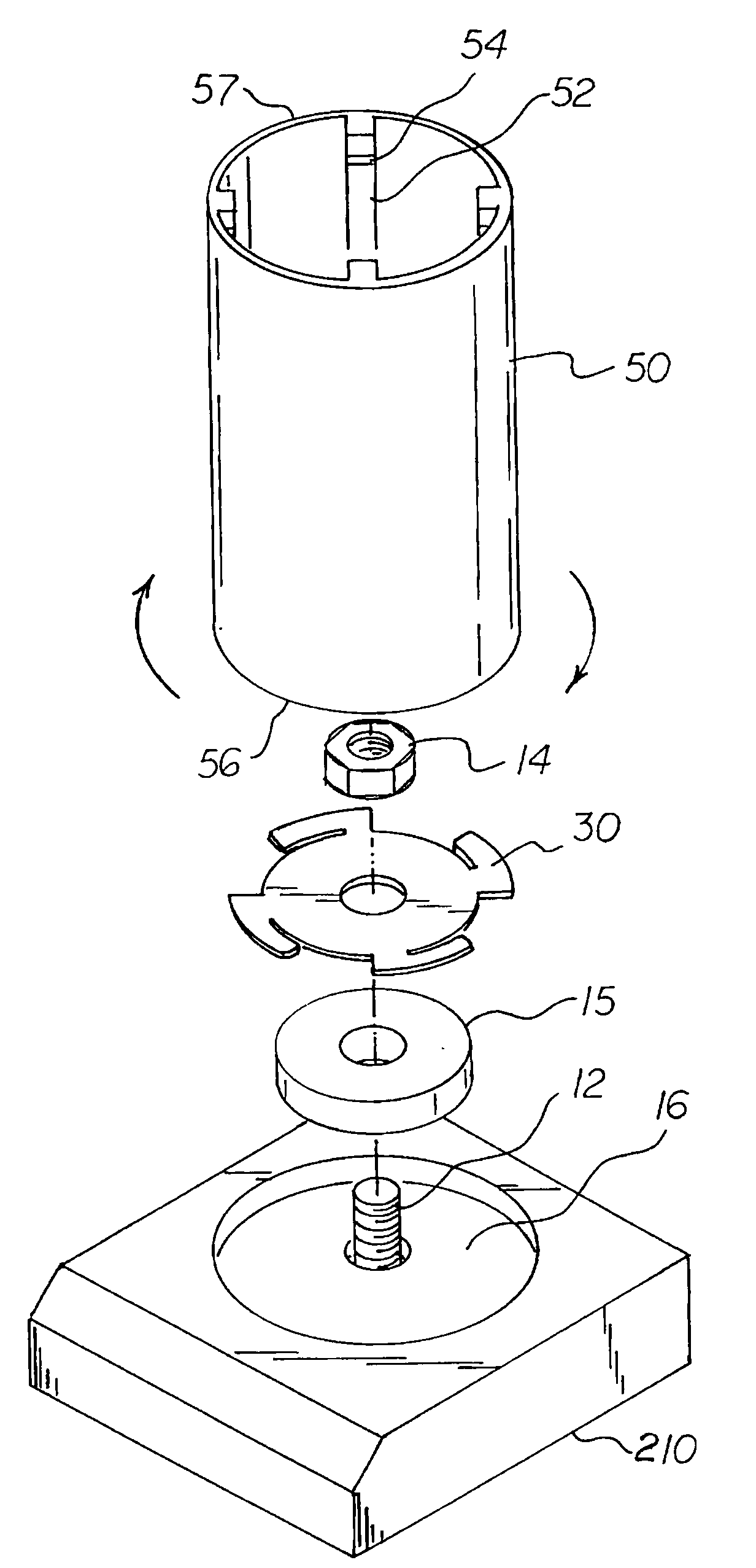
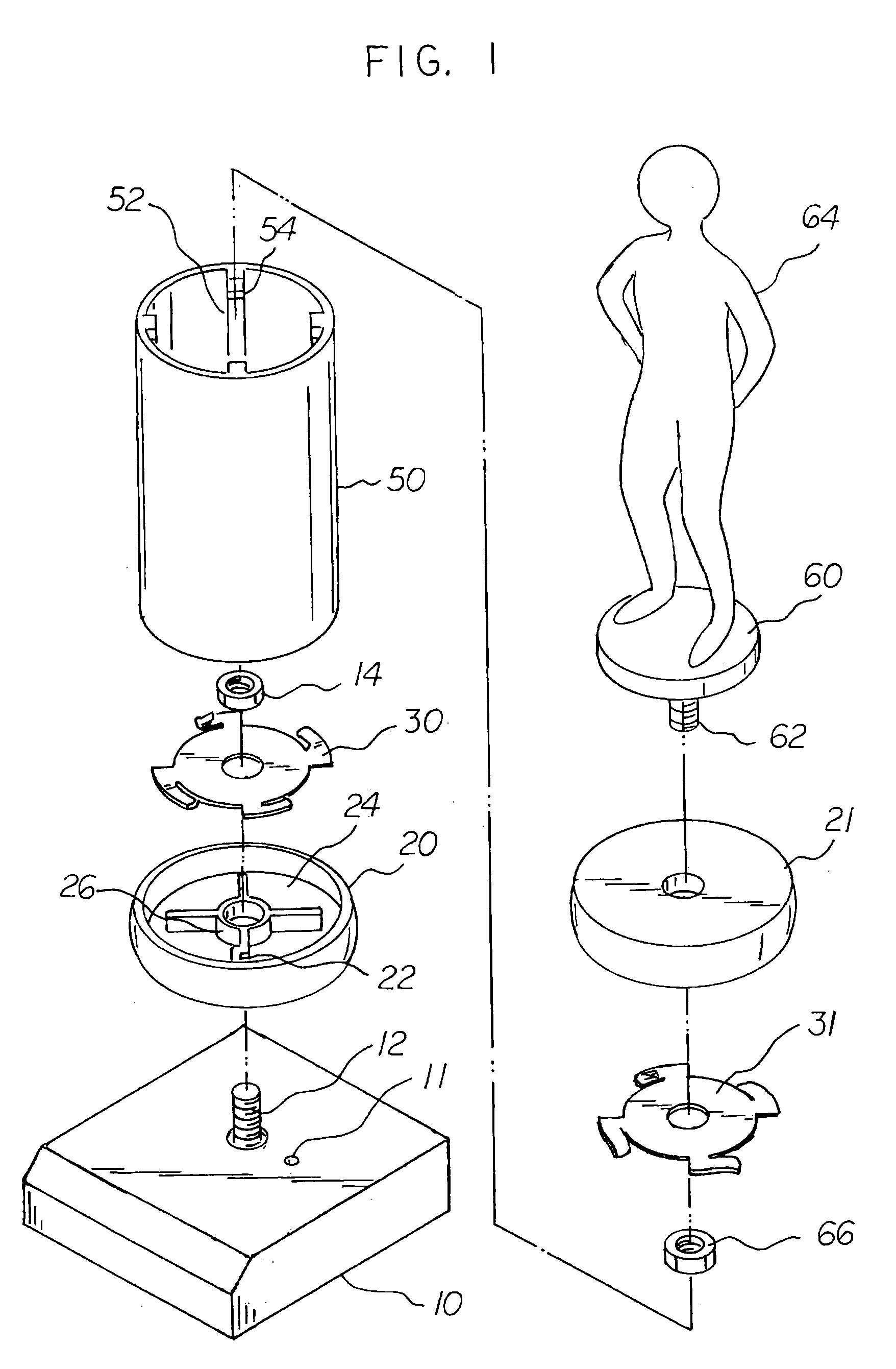
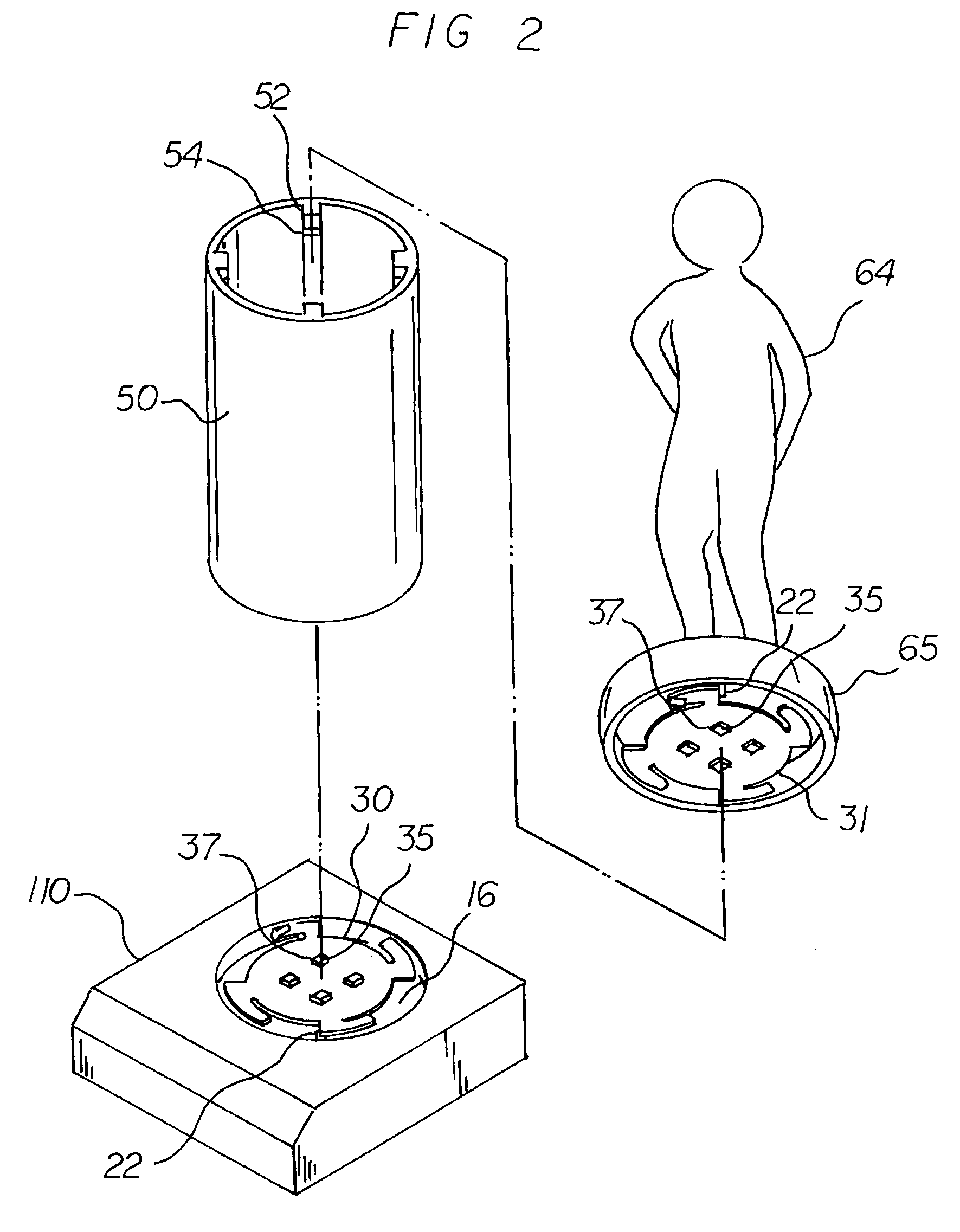
[0028]FIGS. 1-25 illustrate preferred embodiments of the trophy assembly and methods of this invention. This trophy assembly generally comprises a base member 10, 110, 210 a column member 50, and a lower clip member 30 attached to said base member. Each column member 50 is generally hollow and has two ends 56, 57 and an inside surface 58. In this specification, “adapted” shall mean configured, dimensioned, arranged, and oriented as appropriate and, accordingly, column member 50 is preferably in the form of a generally cylindrical, hollow tube, adapted to fit over lower clip member 30 such that column member 50 can be rotated about lower clip member 30. Column member 50 may also conveniently be ellipsoidal, triangular, octagonal, or in many other configurations known in the art, including riser configurations comprising one or two generally cylindrical ends and middle portions of arbitrary shape or design. Column member 50 may conveniently be formed of extruded plastic with at least ...


PUM


Abstract

A trophy assembly including a base, lower clip, and column having inwardly extending ribs adapted to engage the lower clip, wherein the base and column are joined when the column is placed over the lower clip and rotated. A method for assembling trophies including selecting a base, column with internal ribs, and a clip, attaching the clip to the base, forming slots in interior ribs of the column, placing the column over the clip and rotating it, whereby the base and column are joined. A trophy assembly further including upper clips adapted to engage inwardly extending column ribs and attached to upper members, wherein the base, column, and upper member are joined when the column is rotated.

Description

BACKGROUND OF THE INVENTION[0001]This invention relates to trophy assemblies utilizing plastic columns sold by awards dealers and typically used to commemorate sports victories and other achievements.[0002]Typical conventional trophy assemblies comprise a base, a lower lid, a column, an upper lid and a figure symbolic of the achievement. Larger trophy assemblies may comprise additional columns mounted to create multi-level trophies with the figure on the top. Historically, trophies utilizing columns have been assembled using threaded rods that run through the base, the lower lid, the column, the upper lid and then attach to the figure using a coupler. A nut is then used to secure the base to the rod and compress the base, lower lid, column, upper lid, and figure together, thereby creating a rigid assembly.[0003]The conventional threaded rod design has several disadvantages. One disadvantage is that the nut, threaded rod, and coupler (the “hardware”) contribute more than 30% of the n...

Claims


Application Information

Patent Timeline
Patent Type & Authority Applications(United States)
IPC IPC(8): F16M13/00
CPCA47G33/004
Inventor SCHWARTZ, WILLIAM
Owner WILLIAM STEVEN SCHWARTZ REVOCABLE TRUST
Why Eureka
Try Eureka