Slide mechanism for slide-type portable terminal devices

Inactive Publication Date: 2009-06-11
HONG FU JIN PRECISION IND (SHENZHEN) CO LTD +1
View PDF3 Cites 12 Cited by
  • Summary
  • Abstract
  • Description
  • Claims
  • Application Information

AI Technical Summary

Benefits of technology

[0007]An exemplary slide mechanism includes a rear cover, a front cover and two sliding rods. The front cover is slidably connected to the rear cover via the sliding rods. The rear cover includes a first frame positioned in a center of the rear cover, a first magnetic member received in the first frame, and two second magnetic members positioned respectively on opposite sides of the first magnetic member. The front cover includes a second frame positioned in a center of the front cover, a third magnetic member received in the second frame, and two fourth magnetic

Problems solved by technology

Usually, in the hand-over from the initial user's force and the magnetic force the front cov

Method used


Image

  • Slide mechanism for slide-type portable terminal devices
  • Slide mechanism for slide-type portable terminal devices
  • Slide mechanism for slide-type portable terminal devices

Examples


first embodiment

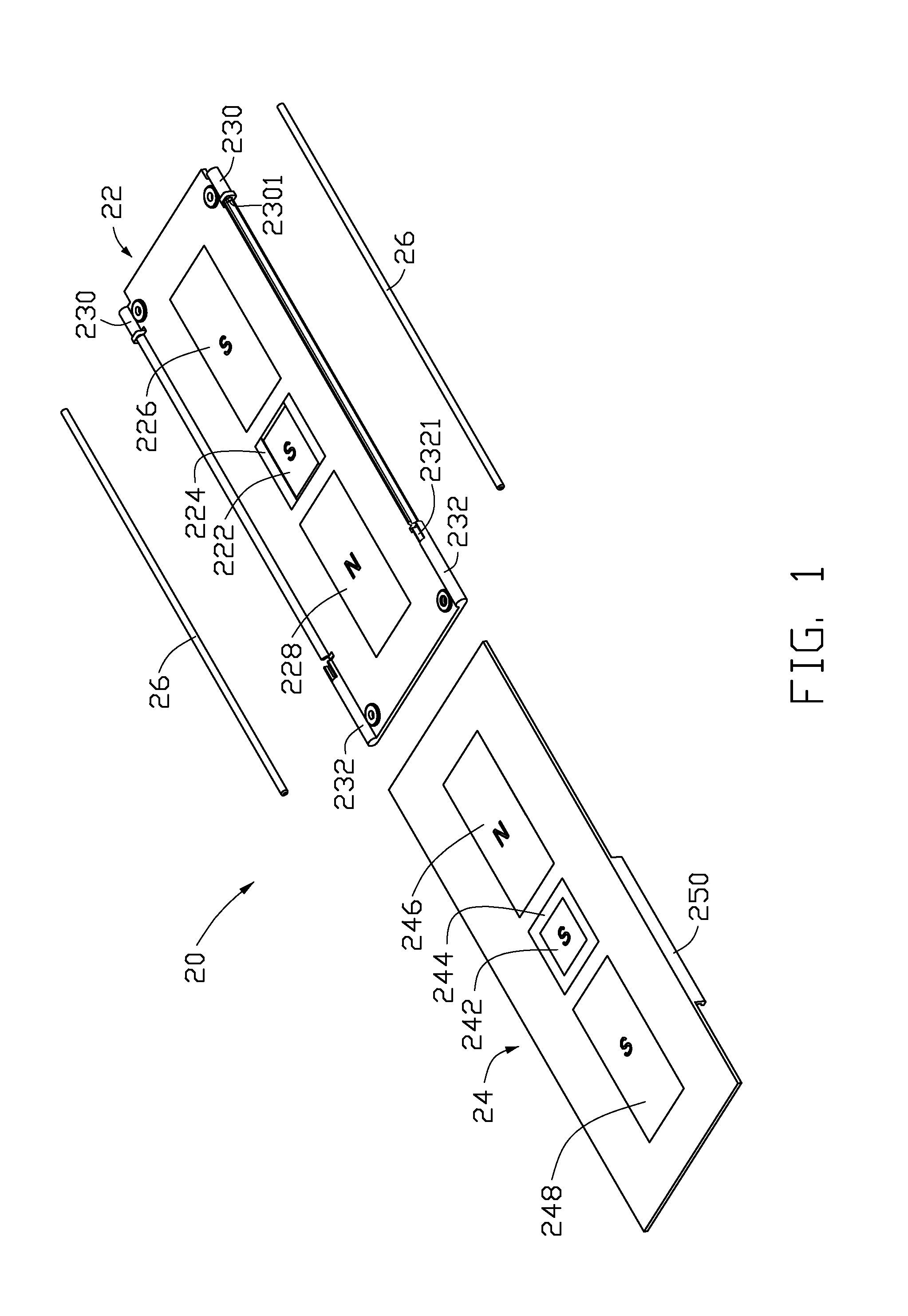
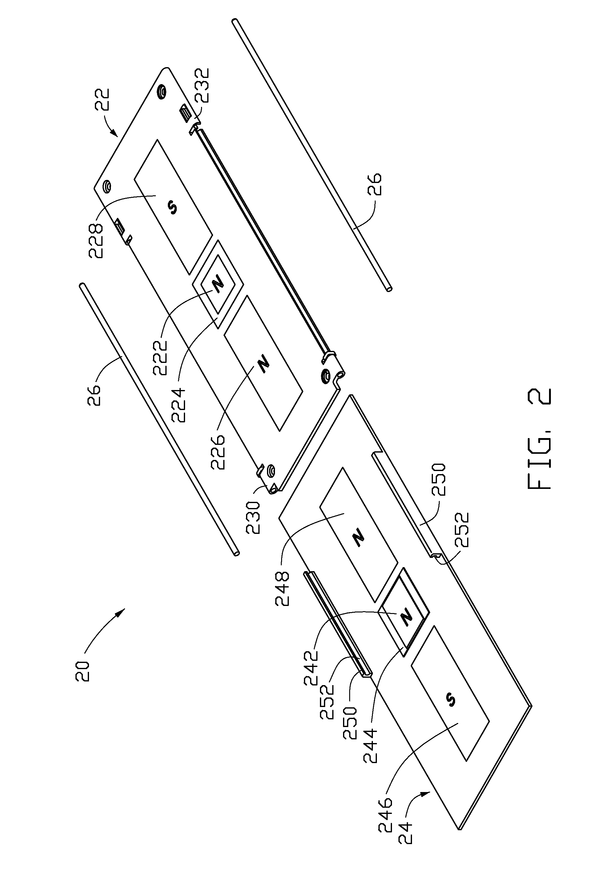
[0020]Referring to FIGS. 1 and 2, a slide mechanism 20 of a first embodiment includes a rear cover 22, a front cover 24, and two sliding rods 26.

[0021]The rear cover 22 is substantially a rectangular plate and includes a first magnetic member 222, a first frame 224, two second magnetic members 226, 228, two first positioning pins 230, and two second positioning pins 232.

[0022]The magnetic members 222, 226, 228 are rectangular magnets. The first magnetic member 222 is positioned on a center of the rear cover 22. The second magnetic members 226, 228 are positioned on opposite sides of the first magnetic member 222 and lengthwise of the rear cover 22.

[0023]Referring to FIG. 3, the first frame 224 includes four sidewalls 2242 cooperatively defining a rectangular hole 2240 for receiving the first magnetic member 222. The first frame 224 further includes two recessed portions 2244 defined in two sidewalls 2242 on opposite sides of the first frame 224 correspondingly.

[0024]Referring again ...

second embodiment

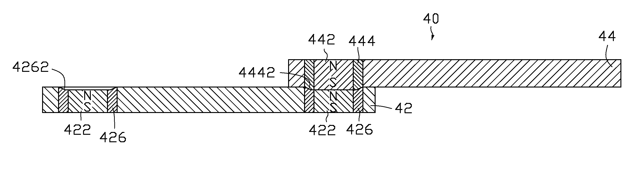
[0036]Referring to FIG. 7, a slide mechanism 40 of a second embodiment is shown. The slide mechanism 40 includes a rear cover 42 and a front cover 44. The rear cover 42 includes two first frames 426 and two first magnetic members 422 received in the two first frames 426 respectively, and the two first frames 426 together with the two first magnetic members 422 are mounted in two ends of the rear cover 42. The front cover 44 includes a second frame 444 and a second magnetic member 442 received in the second frame 444, and the second frame 444 together with the second magnetic member 442 is mounted in an end of the cover 44. A recessed portion 4262 is defined in each of the first frames 426. A protruding portion 4442 is formed on the second frame 444 to engage with the recessed portion 4262. In addition, portions of the each first magnetic member 422 and the second magnetic member 442 facing each other have an opposite polarity, such that the first and second magnetic members 422, 442...

third embodiment

[0038]Referring to FIG. 9, a slide mechanism 60 of a third embodiment is shown. The slide mechanism 60 includes a rear cover 62 and a front cover 64. The rear cover 62 includes a first magnetic member 622 positioned in a center and two recessed portions 624 positioned in two ends of the rear cover 62. The front cover 64 includes a second frame 644 and a second magnetic member 642 received in the second frame 644, and the second frame 644 together with the second magnetic member 642 is mounted in an end of the front cover 64. A protruding portion 6442 is formed on the second frame 644, and the protruding portion 6442 can engage in each of the recessed portions 624 of the rear cover 62. In addition, portions of the first and second magnetic members 622, 642 facing each other have a same polarity, such that the first and second magnetic members 622,642 repel each other.

[0039]The slide mechanism 60 can be opened / closed automatically via a magnetic repelling force created by the first an...


PUM


Abstract

A slide mechanism (20) includes a rear cover (22), a front cover (24) slidably connected to the rear cover, and at least two magnetic members positioned on the rear cover and the front cover respectively. The front cover can be opened/closed relative to the rear cover semi-automatically via a magnetic force created by the at least two magnetic members. One of the front cover and the rear cover forms at least one protruding portion, and the other one of the front cover and the rear cover defines at least one recessed portion for engaging with the protruding portion. When the front cover is slid to an opened or closed position, the at least one protruding portion engages in the at least one recessed portion correspondingly.

Description

BACKGROUND OF THE INVENTION[0001]1. Field of the Invention[0002]The present invention relates to slide mechanisms, and more particularly to a slide mechanism for a slide-type portable terminal device.[0003]2. Discussion of the Related Art[0004]Slide-type portable terminal devices, for example slide-type mobile phones are popular. The slide-type portable terminal has two housings. One housing slides over the other housing, thereby opening or closing the portable terminal device.[0005]A typical slide mechanism includes a rear cover, a front cover slidably mounted on the rear cover, and two magnetic members positioned on the front cover and the rear cover, respectively. The front cover can be opened / closed relative to the rear cover semi-automatically via a magnetic force created by the two magnetic members. In the fully closed or fully open position of the front cover, the user applies an initial force to the front cover to move the front cover a predetermined distance. When the front...

Claims


Application Information

Patent Timeline
IPC IPC(8): A47B88/04
CPCH04M1/0237
Inventor WANG, JIN-XIN
Owner HONG FU JIN PRECISION IND (SHENZHEN) CO LTD
Why Eureka
Try Eureka