
Radio frequency coaxial connector and application method thereof

A radio frequency coaxial and connector technology, applied in the direction of connection, two-part connection device, assembly/disassembly of contacts, etc., can solve the problems of radial shaking, affecting reliability, poor waterproofness of connectors, etc., to prevent shaking and shaking , the effect of improving tensile strength and improving reliability

Inactive Publication Date: 2013-01-30
PCT BROADBAND COMM YANTAI
View PDF6 Cites 2 Cited by
  • Summary
  • Abstract
  • Description
  • Claims
  • Application Information

AI Technical Summary

Problems solved by technology

[0002] RF coaxial connectors are mechanical and electrical integration products, usually installed on cables or instruments, as components for electrical connection or separation of transmission lines, it can effectively transmit electromagnetic wave signals and energy, with the rapid development of the communication industry, especially wired Widely demanded by the TV industry, RF coaxial connectors are more and more widely recognized in the industry. The main problem of existing RF coaxial connectors is that the tensile resistance is not strong enough. When the external pulling force is large, it is easy to The overall dispersion of the connector affects the transmission effect, and when the conductor is passed through the connector, because the conductor and the connector are a socket structure, it is easy to cause the axial movement and radial movement of the conductor, which affects the overall reliability , In addition, the waterproof performance of the connector is also poor. Due to the above shortcomings, the RF coaxial connector also has great limitations in actual use.

Method used


Image

  • Radio frequency coaxial connector and application method thereof
  • Radio frequency coaxial connector and application method thereof
  • Radio frequency coaxial connector and application method thereof

Examples


Embodiment Construction

[0017] The specific embodiments of the present invention are given below with reference to the accompanying drawings, which are used to further describe the composition of the present invention in detail.

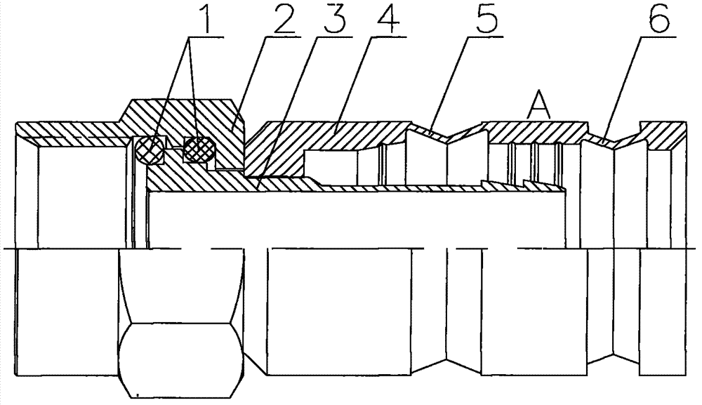
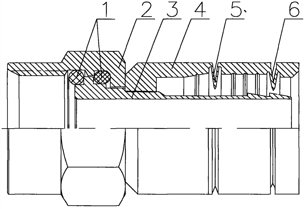
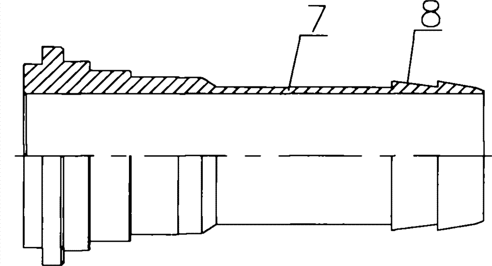
[0018] The radio frequency coaxial connector of this embodiment includes a nut 2, a bushing 3 is sleeved inside the nut 2, a sealing ring 1 for waterproof is provided between the nut 2 and the bushing 3, and an outer casing 4 is clamped on the outer periphery of the bushing 3 , the middle part of the bushing 3 is provided with a reverse tensile groove 7, the end of the bushing 3 is provided with a stepped step 8, the middle part and the rear part of the outer shell 4 are respectively processed with a first V-shaped groove 5 and a second V-shaped groove 6, the second The distance between the top of a V-shaped groove 5 and the reference plane A is 0.01 mm, the angle of the first V-shaped groove 5 is 134 degrees, and the distance between the top of the second V-shaped groove 6 ...


PUM


Abstract

The invention relates to a radio frequency coaxial connector and an application method thereof, and belongs to the technical field of electronic components. The radio frequency coaxial connector comprises a nut, wherein a lining is sleeved in the nut; a waterproof sealing ring is arranged between the nut and the lining; an outer shell is clamped on the periphery of the lining; a reverse tensile groove is arranged in the middle of the lining; a step is arranged at the tail end of the lining; and a first V-shaped groove and a second V-shaped groove are respectively processed on the middle and rear parts of the outer shell. According to the radio frequency coaxial connector, two V-shaped grooves are processed on the outer shell and are extruded by using an extruder, so that the conductors sleeved in the grooves can be tightly pressed and are prevented from swinging, and the reliability of the equipment is improved; and the reverse tensile groove is arranged on the lining, so that the tensile property of the connector is improved. Through the overall design, the radio frequency coaxial connector can be widely applied in the communication industry.

Description

technical field [0001] The invention relates to a radio frequency coaxial connector and a using method thereof, and belongs to the technical field of electronic components. Background technique [0002] RF coaxial connectors are mechanical and electrical integration products, usually installed on cables or instruments, as components for electrical connection or separation of transmission lines, it can effectively transmit electromagnetic wave signals and energy, with the rapid development of the communication industry, especially wired Widely demanded by the TV industry, RF coaxial connectors are more and more widely recognized in the industry. The main problem of existing RF coaxial connectors is that the tensile resistance is not strong enough. When the external pulling force is large, it is easy to The overall dispersion of the connector affects the transmission effect, and when the conductor is passed through the connector, because the conductor and the connector are a s...

Claims


Application Information

Patent Timeline
Patent Type & Authority Applications(China)
IPC IPC(8): H01R13/52H01R13/40H01R43/24H01R24/40
Inventor 程永江谢勇陈超
Owner PCT BROADBAND COMM YANTAI
Learn More