
Connector

Inactive Publication Date: 2009-06-11
HOSIDEN CORP
View PDF9 Cites 4 Cited by
  • Summary
  • Abstract
  • Description
  • Claims
  • Application Information

AI Technical Summary

Benefits of technology

[0010]Accordingly, it is possible to provide a connector in which the engagement projection part of a plug can reliably engage with the engagement hole of a receptacle when the plug is reverse-mounted.
[0012]According to the above aspect, the cutout pieces are caused to lock into the substrate, whereby the receptacle can be reliably mounted on the substrate.
[0014]According to the above aspect, the cutout pieces are not entirely inserted into the substrate, but have a portion which is not inserted into the substrate. Therefore, the shield cover will assume a state of being suspended above the substrate by an amount corresponding to the uninserted portion. As a result, even in a state where the plug has been inserted into the receptacle in a reverse-mounted form and the engagement projection part of the plug has engaged with the engagement hole of the shield cover, a space sufficient to prevent the engagement projection part from interfering with the substrate will be ensured between the region to which the engagement hole is provided and the substrate.

Problems solved by technology

Therefore, the engagement projection part of the plug will interfere with the substrate, and a problem will arise in that the engagement projection part cannot reliably engage with the engagement hole.

Method used


Image

  • Connector
  • Connector
  • Connector

Examples


first embodiment

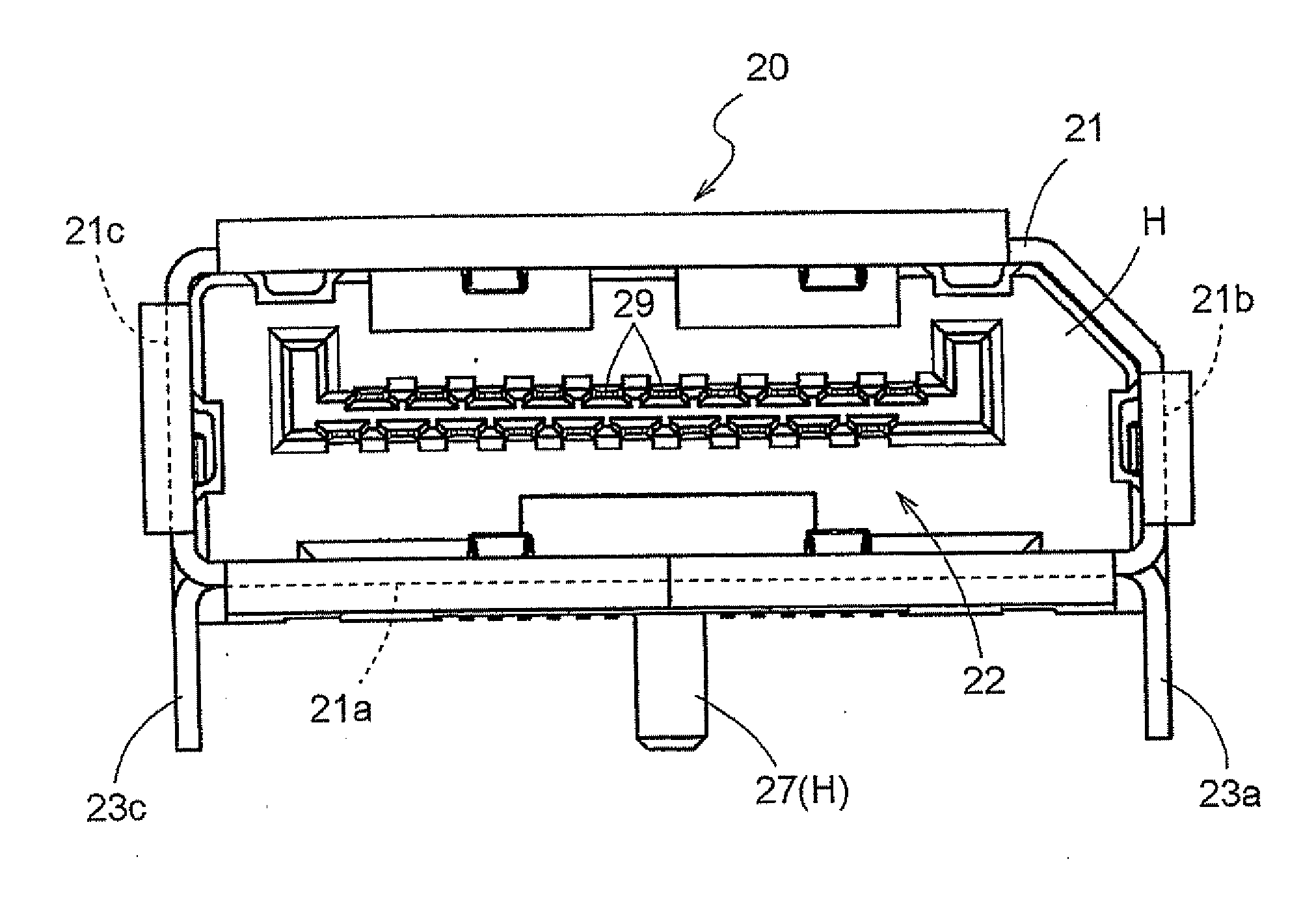
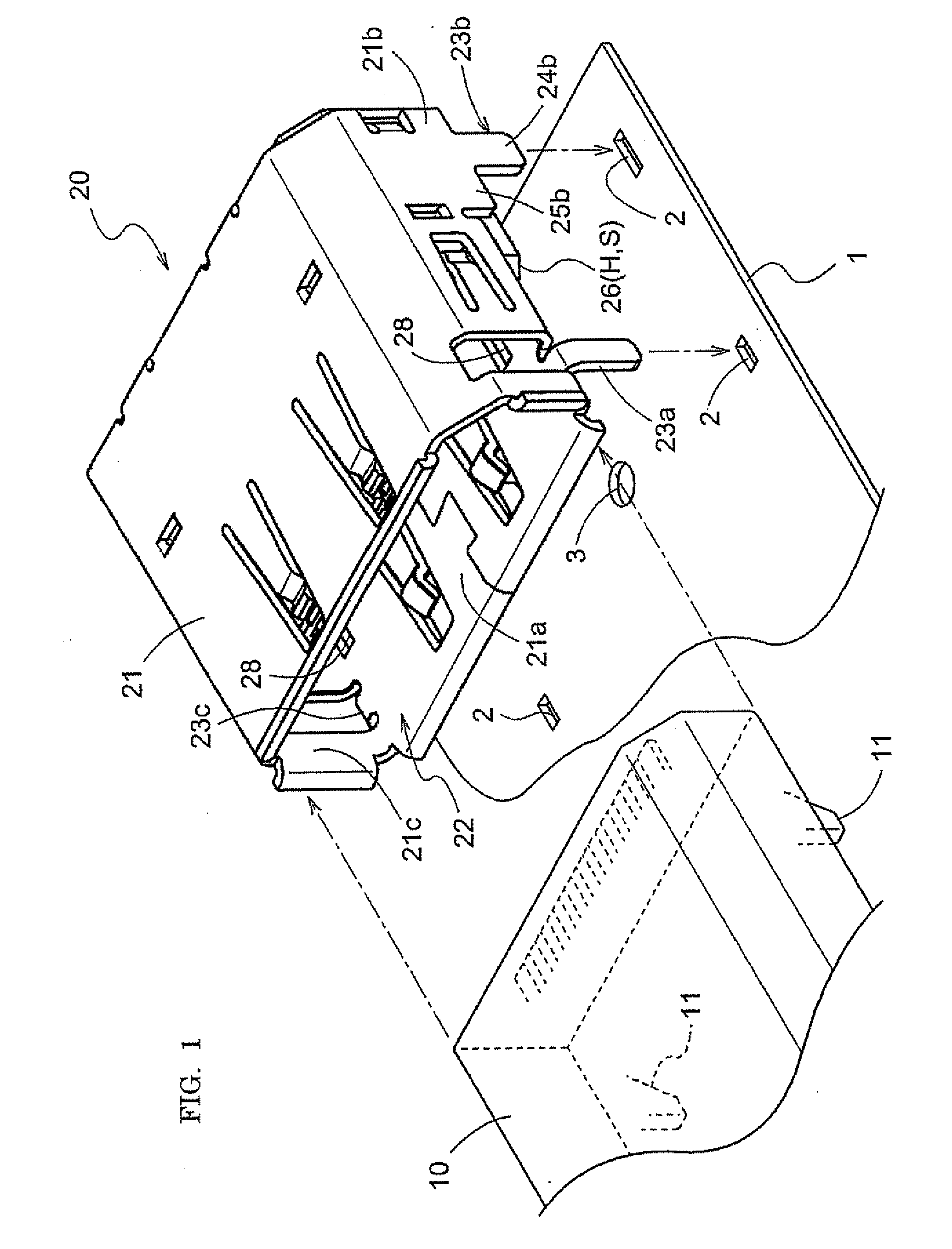
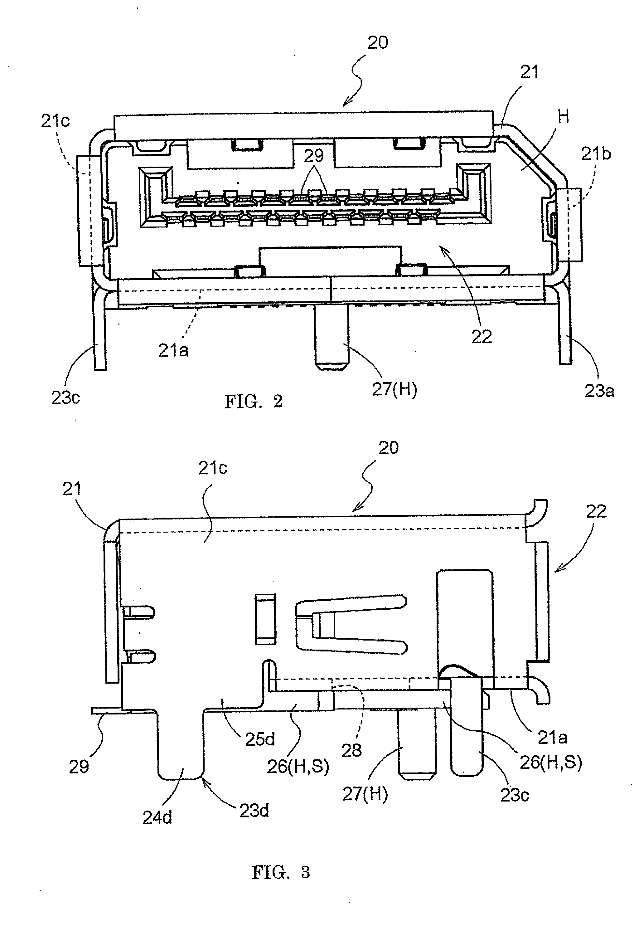
[0027]The following is a description of a connector according to the first embodiment, with reference to the accompanying drawings. The connector according to the present embodiment comprises a plug 10, and a receptacle 20 mounted on a substrate 1 and having an opening 22 into which the plug 10 is inserted. FIG. 1 is a perspective view of the receptacle 20 provided to the connector of the first embodiment. FIG. 2 is a front view of the receptacle 20, FIG. 3 is side view of the receptacle 20, and FIG. 4 is a bottom view of the receptacle 20. FIG. 5 is a cross-sectional view showing a state in which the plug 10 has been inserted into the receptacle 20.

[0028]As shown in FIGS. 1 to 5, a shield cover 21 formed by bending a metallic plate constitutes the exterior of the receptacle 20. The shield cover 21 is formed into a tubular body that is rectangular in cross-section, and accommodates a resin-formed housing H in an interior thereof. The housing H holds a receptacle-side terminal part 2...

second embodiment

[0041]The receptacle in the connector according to the second embodiment has a structure that differs from the structure of the receptacle described in the first embodiment. A description of the connector according to the second embodiment is provided below; however, descriptions of structures that are the same as in the first embodiment have not been provided.

[0042]FIG. 6 is a side view of the receptacle 20 of the second embodiment. FIG. 7 is a cross-sectional view of a state in which the plug 10 has been inserted into the receptacle 20. As illustrated in the drawings, the receptacle 20 of the connector of the present embodiment does not have the spacer member 26 described in the first embodiment. Specifically, the spacer member 26 that can be used as the abovementioned space-retaining part S is not present between the shield cover 21 and the substrate 1.

[0043]The present embodiment is configured so that the base parts 25a, 25c of the cutout pieces 23a, 23c are formed wider than th...


PUM


Abstract

A connector comprises a plug, and a receptacle mounted on a substrate and having an opening into which the plug is inserted. The receptacle has a housing for holding a receptacle-side terminal part in an interior of a tubular shield cover that forms the opening. An engagement projection part provided to the plug engages with an engagement hole provided to a region of the shield cover of the receptacle that faces the substrate when the plug is inserted into the receptacle, and in a state in which the receptacle is mounted on the substrate, the region of the shield cover to which the engagement hole is provided is positioned away from the substrate by a set distance.

Description

BACKGROUND OF THE INVENTION[0001]1. Field of the Invention[0002]The present invention relates to a connector comprising a plug and a receptacle mounted on a substrate and having an opening into which the plug is inserted, and relates more particularly to a connector constructed so that the receptacle has a housing for holding a receptacle-side terminal part in the interior of a tubular shield cover that forms an opening, and when the plug is inserted into the receptacle an engagement projection part provided to the plug engages with an engagement hole provided to the receptacle.[0003]2. Description of the Related Art[0004]Connectors comprising a plug and a receptacle are used for connecting a variety of devices to wiring patterns on circuit boards in the interior of a variety of electrical devices. For example, a plug is provided to a distal end of wiring linked to a device, a receptacle is provided on the wiring pattern of a circuit board, and the plug is inserted into the receptac...

Claims


Application Information

Patent Timeline
IPC IPC(8): H01R24/00
CPCH01R13/627H01R13/62H01R13/639H01R13/648
Inventor KONDO, HAYATONAGATA, TAKAYUKIOHTSUJI, TAKAHISA
Owner HOSIDEN CORP
Learn More