
Paper discharge device for printer

Inactive Publication Date: 2005-11-03
FUNAI ELECTRIC CO LTD
View PDF12 Cites 0 Cited by
  • Summary
  • Abstract
  • Description
  • Claims
  • Application Information

AI Technical Summary

Benefits of technology

[0011] It is another object of the present invention to provide a paper discharge device for printer, in which in the case where a single motor is required as a rotary drive source for the paper feed roller 1 and the paper discharge roller 5 to limit the required number of motors to one, the arrangement of a transmission mechanism between the paper feed roller and the paper discharge roller for feeding and discharging paper without switching the rotation direction of the motor can be simplified easily.
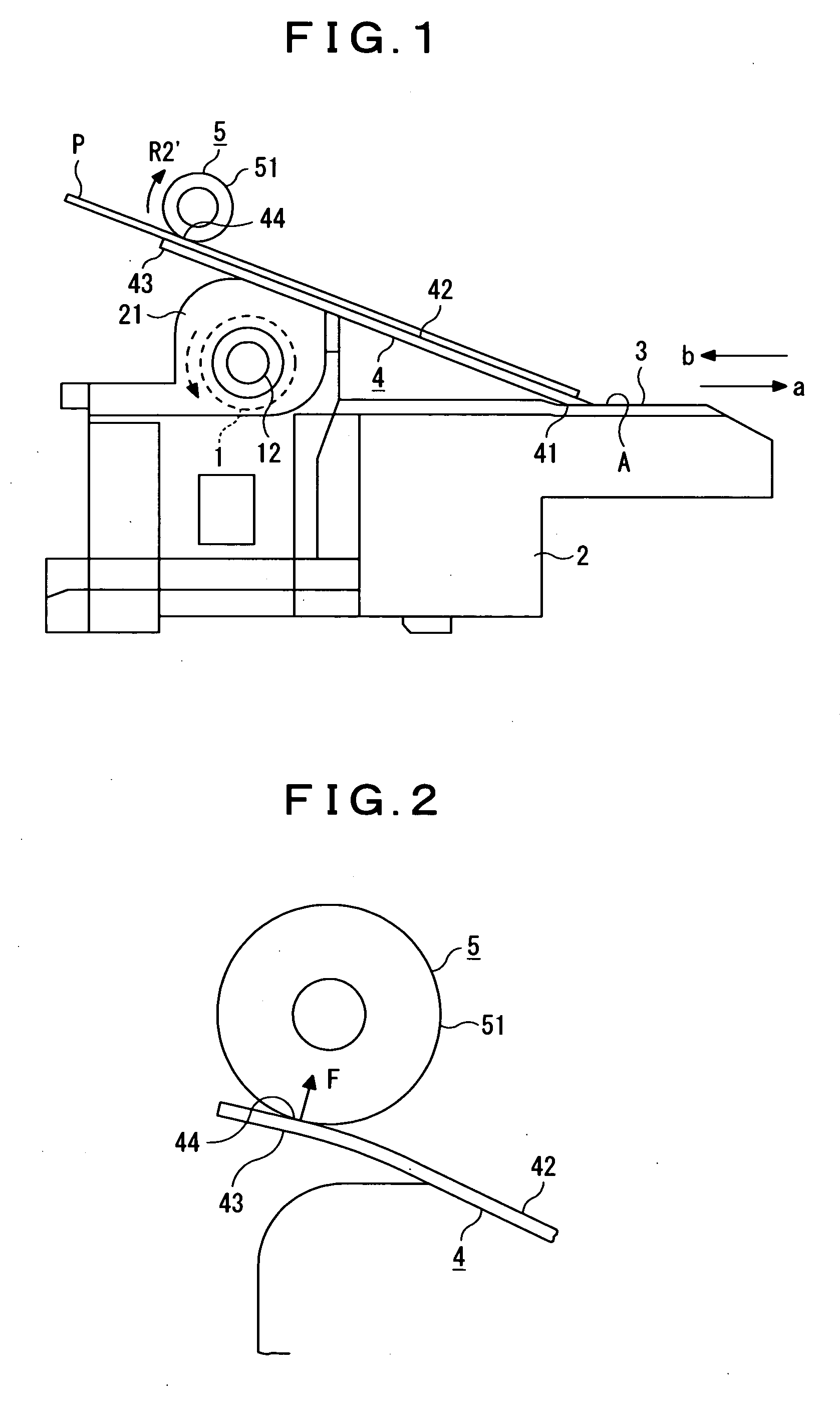
[0013] In accordance with the invention above, the plate piece forming the paper guide includes the paper pressing portion, which is adapted to bring paper running on to the paper discharge surface formed by one surface of the plate piece into elastic contact by the elasticity of the plate piece, whereby the function offered by the paper pressing member 6 described in FIG. 4 is to be offered by the paper pressing portion of the paper guide instead. Therefore, it is not necessary to use the paper pressing member 6 as an additional part, resulting in a reduction of the number of parts, and also to ensure an additional space for installing the paper pressing member 6.
[0014] Further in accordance with the arrangement above, the paper running on to the paper discharge surface is brought upward into elastic contact with the circumferential surface of the paper discharge roller, whereby in the case where a single motor is required as a rotary drive source for the paper feed roller and the paper discharge roller to limit the required number of motors to one, it is possible to feed and discharge paper without switching the rotation direction of the motor by engaging an input gear on the side of the paper feed roller and an output gear on the side of the paper discharge roller directly with each other. Therefore, it is not necessary to use additionally the relay gear 73 shown in FIG. 5(A) with respect to the conventional paper discharge device, resulting in a reduction of the number of parts, and also to ensure an additional space for installing the relay gear 73, which allows the reduction of the size of the paper discharge device to be promoted easily. In addition, it is not necessary to select the feed mode or the discharge mode alternatively by switching the rotation direction of the motor as described with reference to FIG. 5(B).
[0015] A paper discharge device according to the present invention can be specified more clearly by employing the arrangement that in the paper discharge device for printer having a paper guide that comprises a paper holding portion for holding paper fed by a paper feed roller with a paper guide surface therebetween at a longitudinally intermediate position of the paper guide surface in front of the paper feed roller while the paper passes therethrough in the feed direction, the paper guide is formed by a flat plate piece composed of an elastic resin plate, one surface of the plate piece being formed as a paper discharge surface that allows paper carried through on the paper guide surface in front of the paper holding portion in the discharge direction opposite to the feed direction to run on thereto, and the plate piece being provided from the paper guide surface through above the paper feed roller with the rear portion thereof raised, and a paper discharge roller for applying a carrying force to the paper running on to the paper discharge surface in the discharge direction is provided opposite above an extension portion included in the plate piece by extending the plate piece rearward, the extension portion including a paper pressing portion for bringing upward the paper running on to the paper discharge surface into elastic contact with the circumferential surface of the paper discharge roller by the elasticity of the plate piece while the paper passes therethrough.
[0016] As described heretofore, in accordance with the present invention, one surface of the paper guide is utilized as the paper discharge surface for guiding paper in the discharge direction, and the paper guide is also used as a replacement for the paper pressing member 6 described in FIG. 4 to allow the paper pressing member 6 as an additional part to be removed, resulting in a reduction of the number of parts, and it is not necessary to ensure an additional space for installing the paper pressing member 6, which allows the reduction of cost and size of the paper discharge device to be promoted easily.
[0017] Further, in the case where a single motor is required as a rotary drive source for the paper feed roller and the paper discharge roller to limit the required number of motors to one, the arrangement of a transmission mechanism between the paper feed roller and the paper discharge roller for feeding and discharging paper without switching the rotation direction of the motor can be simplified easily.

Problems solved by technology

However, the arrangement, as shown in the prior art example described in FIG. 4 or the above-described antecedents, that paper is brought into elastic contact with the paper discharge roller 5 using the paper pressing member 6 or a member corresponding thereto, and then the paper discharge roller 5 applies a carrying force to the paper in the discharge direction requires the paper pressing member 6 or the member corresponding thereto additionally, resulting in a cost increase and in a problem in that it is necessary to ensure an additional space for installing the paper pressing member 6, inhibiting the reduction of the size of the paper discharge device.
On the contrary, selecting the feed mode and the discharge mode alternatively by switching the rotation direction of the motor suffers from a problem in that the technique for controlling the rotation direction of the motor becomes complicated.

Method used


Image

  • Paper discharge device for printer
  • Paper discharge device for printer
  • Paper discharge device for printer

Examples


Embodiment Construction

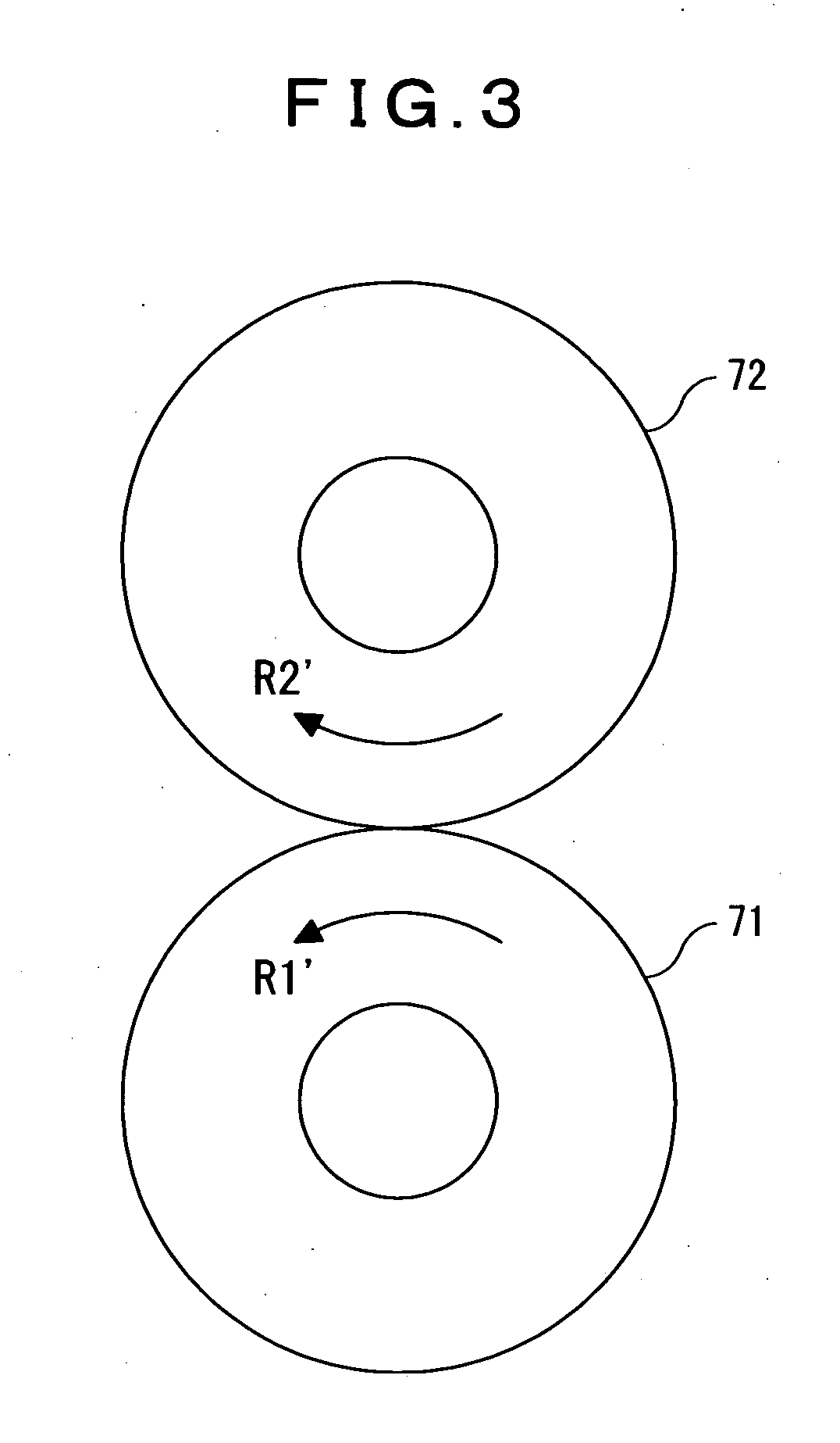
[0024]FIG. 1 is a schematic side elevational view of a paper discharge device for printer according to the present invention, FIG. 2 is an enlarged view of a substantial part of the paper discharge device, and FIG. 3 is an illustrative view showing an example of a transmission mechanism.

[0025] The paper discharge device shown in FIG. 1 has the same arrangement as the prior art example described in FIG. 4 in that on the upper surface of a base member 2 with a paper feed roller 1 mounted thereon is formed a paper guide surface 3 for guiding paper, which is fed in the feed direction (forward) “a” by the paper feed roller 1, slidingly toward a print section (not shown in the figure); that from a bearing portion 21 of the base member 2, which holds rotatably a spindle 12 supporting the paper feed roller 1, through a longitudinally intermediate position A of the paper guide surface 3 is arranged a paper guide 4 formed by a plate piece with the rear portion thereof raised, the front end p...


PUM

PropertyMeasurementUnit
Elasticityaaaaaaaaaa

Abstract

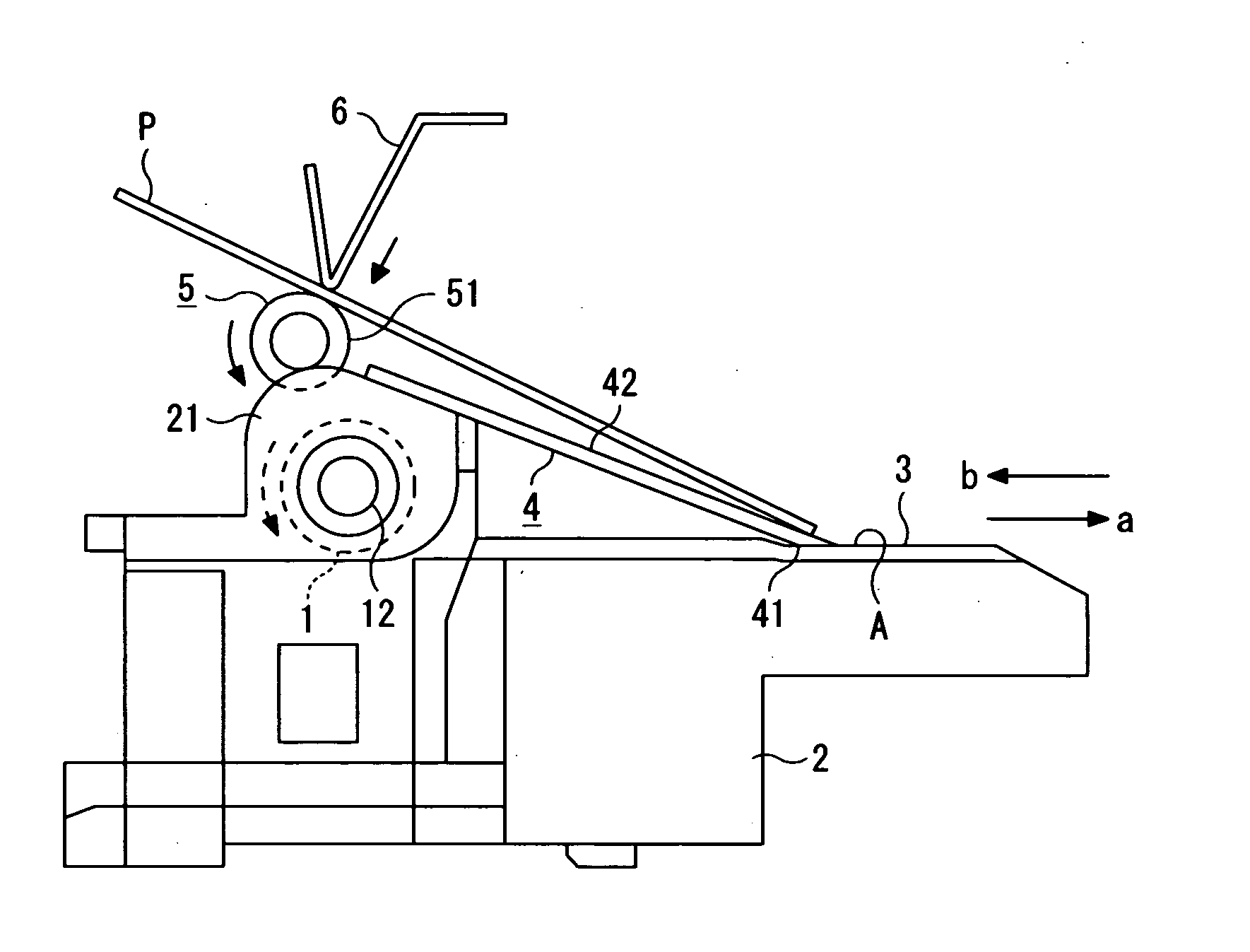
A paper discharge device for printer according to the present invention has a paper guide 4 that comprises a paper holding portion 41 for holding paper P with a paper guide surface 3 therebetween at a longitudinally intermediate position A of the paper guide surface 3 in front of a paper feed roller 1 while the paper P passes therethrough in the feed direction “a”. The paper guide 4 is formed by a resin plate piece, one surface of the plate piece being utilized as a paper discharge surface 42. An extension portion 43 included in the plate piece is provided opposite below a paper discharge roller 5 to bring upward the paper P running on to the paper discharge surface 42 into contact with the circumferential surface 51 of the paper discharge roller 5 by the elasticity of the plate piece. Thus, one surface of the paper guide is utilized as a paper discharge surface, and the paper guide is also used as a paper pressing member for pressing paper against the paper discharge roller.

Description

BACKGROUND OF THE INVENTION [0001] 1. (Field of the Invention) [0002] The present invention relates to a paper discharge device for printer, and more particularly to a paper discharge device for printer adapted to bring paper into elastic contact with a paper discharge roller to apply a carrying force to the paper in the discharge direction. [0003] 2. (Description of the Prior Art) [0004] In FIG. 4 is shown a schematic side elevational view of a conventional paper discharge device. In the paper discharge device shown in the figure, on the upper surface of a base member 2 with a paper feed roller 1 mounted thereon is formed a paper guide surface 3 for guiding paper, which is fed by the paper feed roller 1 in the feed direction (forward) “a”, slidingly toward a print section (not shown in the figure), and from a bearing portion 21 of the base member 2, which holds rotatably a spindle 12 supporting the paper feed roller 1, through a longitudinally intermediate position A of the paper g...

Claims


Application Information

Patent Timeline
IPC IPC(8): B41J13/02B65H5/00B41J13/10B65H5/06B65H29/22B65H29/52G03G15/00G03G21/00
CPCB65H5/06B65H2401/115G03G15/6573B65H2801/12B65H2403/942B65H2401/11
Inventor CHIKUMOTO, KOUICHI
Owner FUNAI ELECTRIC CO LTD
Learn More