
Implant Abutment

Active Publication Date: 2015-04-09
EUROPEAN BIOINFORMATICS INSTITUTE
View PDF3 Cites 4 Cited by
  • Summary
  • Abstract
  • Description
  • Claims
  • Application Information

AI Technical Summary

Benefits of technology

The invention is an implant abutment that includes two rotating members. These members can rotate with respect to different axes. The abutment has gear portions on its ends that make it easy to attach to a fixture. This allows for easy placement of the abutment in a patient's mouth. The technical effect of this invention is to provide a more convenient and efficient way to attach a fixture to an implant.

Problems solved by technology

However, in the case of the conventional implant abutment, the driver which is a coupling tool must be located in a vertical direction parallel to the fixture and the implant abutment, and thus, when an implanting location for coupling work is not favorable, it is difficult to ensure a working space for coupling the implant abutment in a mouth of a patient.
Accordingly, the patient may feel physical inconvenience, and furthermore, the opened mouth must be kept for long hours during the coupling operation.

Method used


Image

  • Implant Abutment
  • Implant Abutment
  • Implant Abutment

Examples


Embodiment Construction

Best Mode

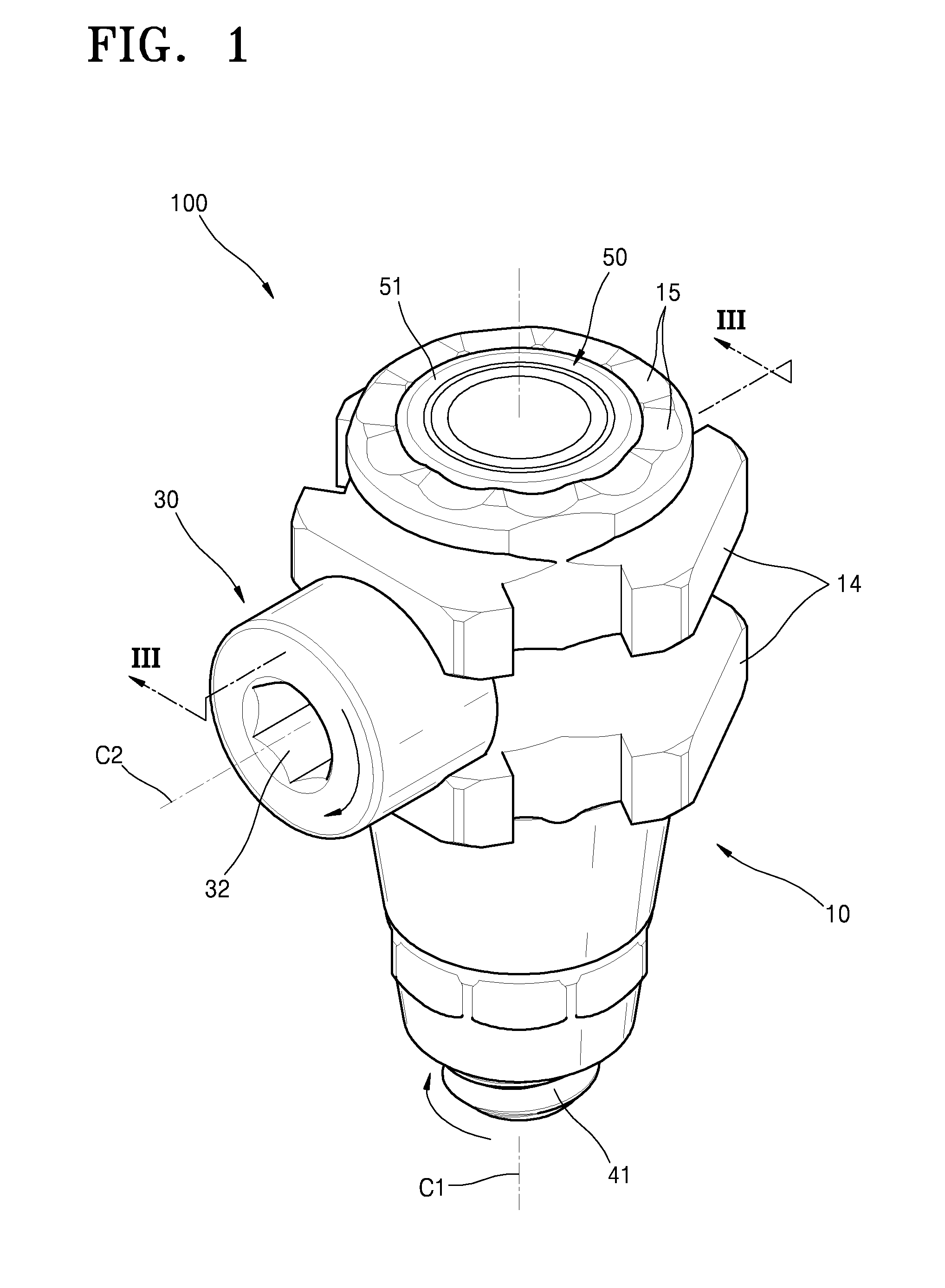
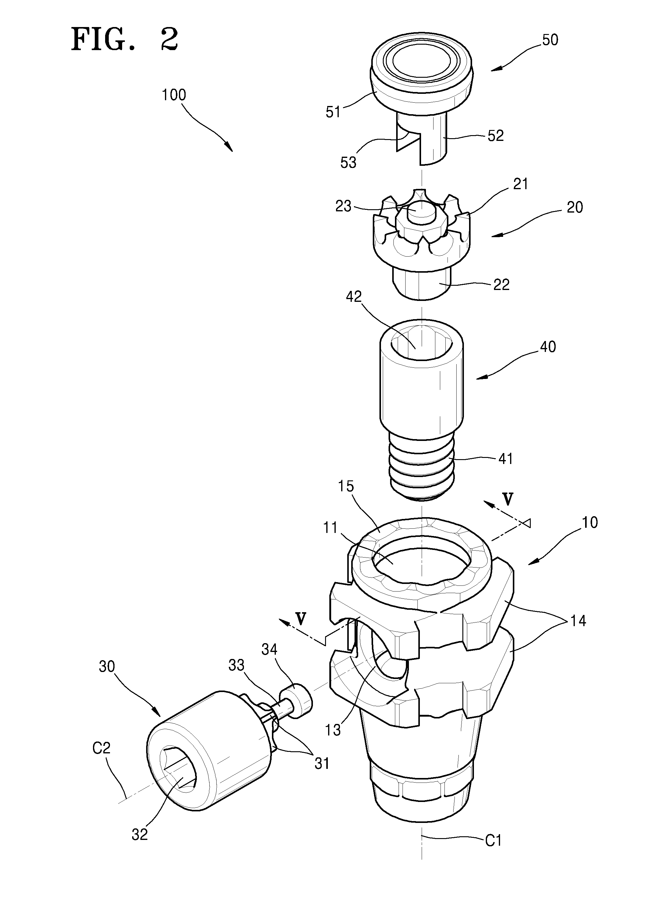
[0031]The present invention will now be described more fully with reference to the accompanying drawings in which exemplary embodiments of the invention are shown.

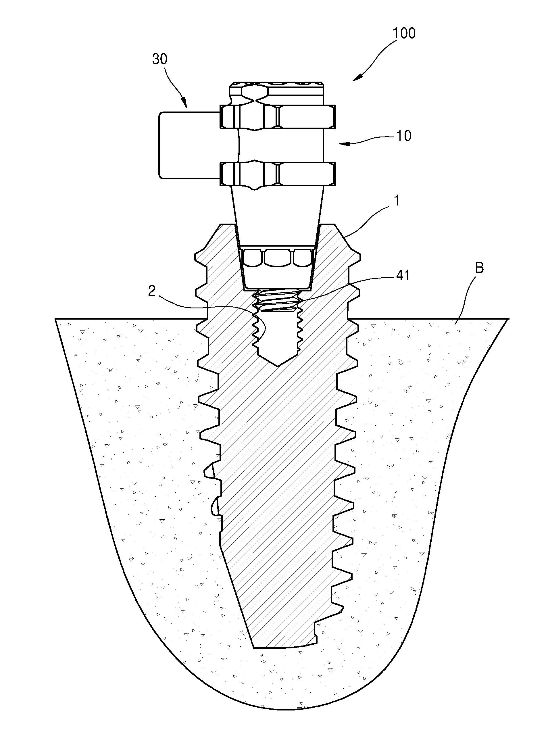
[0032]FIG. 1 is a perspective view of a coupled implant abutment 100 according to an embodiment of the present invention. FIG. 2 is an exploded perspective view of the implant abutment 100 of FIG. 1. FIG. 3 is a cross-sectional view taken along line III-III of FIG. 1.

[0033]Referring to FIGS. 1 through 3, the implant abutment 100 according to an embodiment of the inventive concept includes, a main body 10, a first rotating member 20, a second rotating member 30, a coupling member 40, a stopper member 50, and a derail prevention means as an abutment that is coupled to a fixture 1 that becomes an artificial dental root by being implanted in an alveolar bone B.

[0034]The main body 10 is a cylindrical shape metal housing having an internal space 16. An upper hole 11 and a lower hole 12 are respectively formed on an uppe...


PUM


Abstract

Provided are related to implant abutments. The implant abutment that is coupled to a fixture that becomes an artificial tooth root by being implanted to an alveolar bone, the implant abutment includes: a main body; a first rotating member that is coupled to the main body to be able to rotate with respect to a first rotational axis, includes a first gear portion on an end portion thereof, and includes a male screw portion that is formed on the other end portion thereof to be screw coupled to the fixture; and a second rotating member that is coupled to the main body to be able to rotate with respect to a second rotational axis which crosses the first rotational axis, and includes a second gear portion that is formed on the other end portion thereof to form a bevel gear structure by being coupled to the first gear portion. The implant abutment that can readily ensure a space for coupling work of a fixture in an oral cavity of a patient since a coupling tool, such as a hex screwdriver can be readily placed in a horizontal direction which intersects the direction of implanting the fixture.

Description

FIELD OF THE INVENTION[0001]The inventive concept relates to an implant abutment, and more particularly, to an implant abutment that can readily ensure a space for coupling work of a fixture in an oral cavity of a patient since a coupling tool, such as a hex screwdriver can be readily placed in a horizontal direction which intersects the direction of implanting the fixture.BACKGROUND OF THE INVENTION[0002]A dental implant is referred to as an artificial tooth or a third teeth, and is a therapy method for restoring the function of natural teeth by implanting a biocompatible implant main body in a jawbone where there is a loss of teeth or a tooth is pulled out.[0003]A dental implant generally includes a fixture that is an artificial tooth by being implanted in an alveolar bone; an implant abutment which is an abutment to be screw coupled to an upper part of the fixture; and a crown that is a tooth shape prosthetic appliance to be coupled to an upper part of the abutment.[0004]A conven...

Claims


Application Information

Patent Timeline
IPC IPC(8): A61C8/00
CPCA61C8/0068A61C8/0063A61C8/0001A61C8/0048A61C13/273
Inventor CHO, SANG CHOON
Owner EUROPEAN BIOINFORMATICS INSTITUTE
Learn More