Dust removing device for dust collector

Inactive Publication Date: 2009-06-18
CHENG TJER IND
5 Cites 19 Cited by

AI-Extracted Technical Summary

Problems solved by technology

However, in the typical vacuum collectors, the suction nozzles are only extended toward the drum filter but may not be contacted or engaged with the drum filter such that the waste materials may not be effectively removed from the drum fi...

Benefits of technology

[0010]The primary objective of the present invention is to provide a vacuum or dust collector including a stirring or sweeping or dust removing device...

Abstract

A dust collector includes a filter housing, a filter member disposed in the filter housing, and a dust removing device disposed in the filter member for sweeping the filter member, to sweep of dirt from the filter member, and to allow the dirt to be removed from the filter member. The dust removing device includes one or more actuating members rotatably disposed in the filter member with such as a shaft for engaging with the filter member to sweep of dirt from the filter member when the actuating member is rotated relative to the filter member. A manually operating device is coupled to the shaft for rotating the shaft and the actuating member to sweep off the dust from the filter member.

Application Domain

Dispersed particle filtrationTransportation and packaging +1

Technology Topic

EngineeringDust collector +1

Image

  • Dust removing device for dust collector
  • Dust removing device for dust collector
  • Dust removing device for dust collector

Examples

  • Experimental program(1)

Example

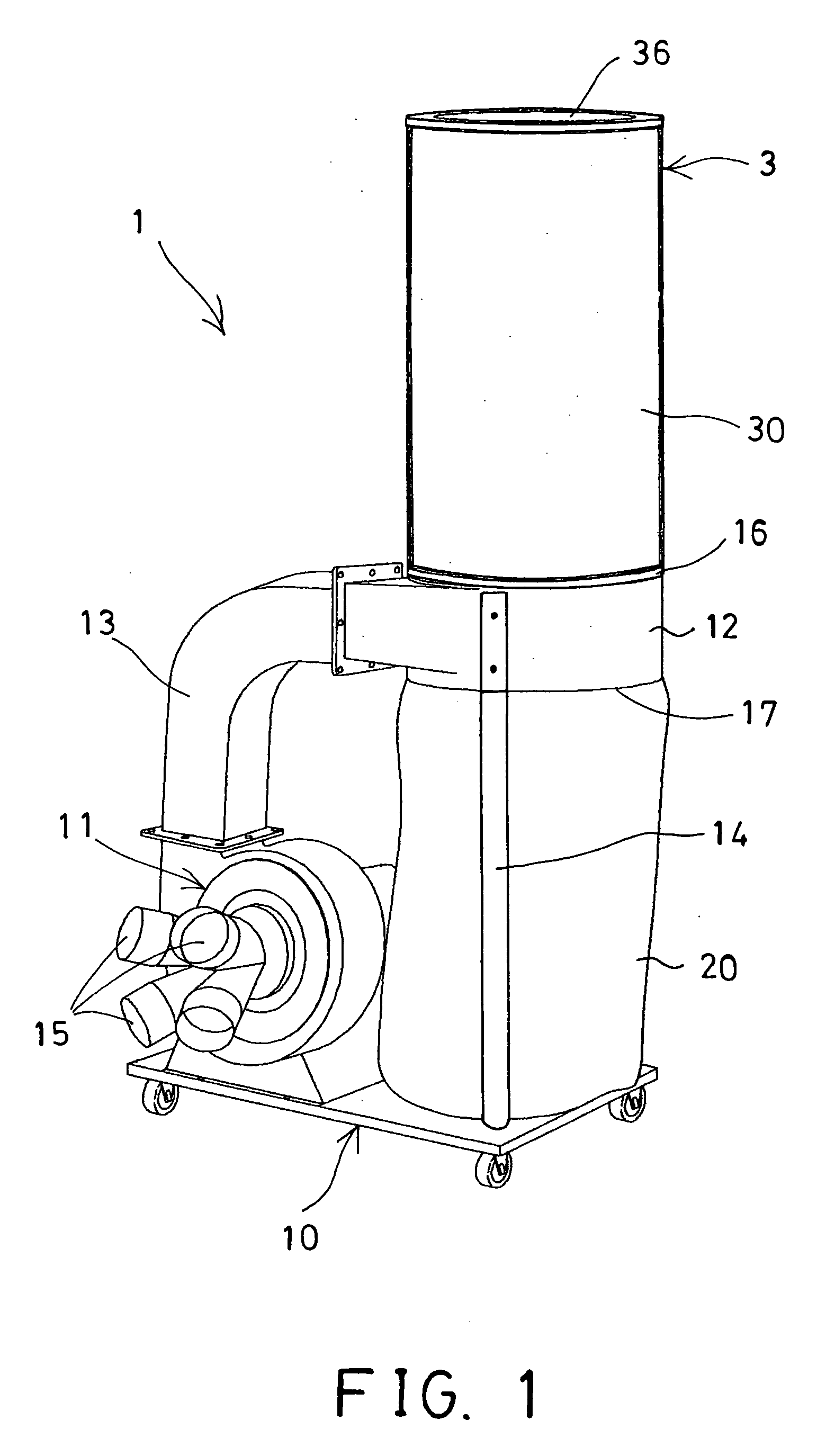
[0023]Referring to the drawings, and initially to FIG. 1, a vacuum collector 1 in accordance with the present invention comprises a base 10, an electric vacuum motor or pump 11 disposed on the base 10 for vacuuming purposes, one or more ducts 12 disposed on the base 10 and coupled to the vacuum pump 11 with manifolds 13 and/or one or more posts 14, and one or more, such as two filter devices 3 attached to the ducts 12 for filtering purposes. The vacuum pump 11 includes one or more ports 15 for coupling to trunks or duct arms or nozzles (not shown) or the like, and for directing toward the dust or dirt or fume to be collected, in order to vacuum or to drawn the dust or the dirt or the fume through the manifolds 13 and the ducts 12 and then into the filter devices 3 which may be provided for filtering and/or collecting the dust or the dirt.
[0024]The filter devices 3 may be attached onto the ducts 12 with such as clamping or retaining rings 16, and preferably disposed above the ducts 12 respectively. One or more dust bags 20 may further be provided and attached onto the ducts 12 with such as clamping or retaining rings 17, and preferably disposed below the ducts 12 and the filter devices 3 respectively, for collecting the dust or the dirt filtered and/or collected by the filter devices 3. As shown in FIGS. 2 and 4, the filter device 3 includes a filter housing 30, and a filter member 31 disposed in the filter housing 30 and preferably snugly fitted within the filter housing 30, or contacted with an inner peripheral surface 32 of the filter housing 30, best shown in FIG. 4. It is preferable that the filter member 31 includes a serrated structure having a number of cusps 33 formed therein and extended inwardly into an inner chamber 34 of the filter member 31, and having a number of recesses 35 formed or defined between the cusps 33.
[0025]The filter housing 30 includes an upper panel 36, and includes a lower bar 37 attached to the bottom portion thereof, and includes two hubs or seats 38 attached to the upper panel 36 and the bar 37 respectively. As shown in FIGS. 2-5, a stirring or sweeping or dust removing device 40 is disposed in the filter housing 30 and the filter member 31, for sweeping the dust or the dirt from the filter member 31 and for allowing the dust or the dirt to be easily removed from the filter member 31 and/or to be easily collected within the dust bag 20. For example, the dust removing device 40 includes a shaft 41 rotatably disposed in the center portion of the filter member 31 and in the filter housing 30, and the shaft 41 includes two ends rotatably secured to the seats 38 with such as bearings 42 or the like. It is preferable that the shaft 41 includes a non-circular cross section, such as a triangular cross section, a square or rectangular cross section, a hexagonal cross section or the like, such that the shaft 41 may include two or more flat surfaces 43 formed thereon. The dust removing device 40 further includes one or more rods or flaps or sweeping or actuating members 44 secured onto the shaft 41, such as secured onto the flat surfaces 43 of the shaft 41. When the shaft 41 includes a triangular or a hexagonal cross section having three or six flat surfaces 43 formed thereon, it is preferable, but not necessarily that the actuating members 44 are secured onto the shaft 41 and arranged to have a 120° included angle formed therebetween or arranged toward different directions. The dust removing device 40 further includes one or more blades 45 of such as rubber or resilient materials secured to the free ends of the actuating members 44 for engaging with the filter member 31, such as for engaging with the cusps 33 of the filter member 31, in order to stir or to sweep off the dust or the dirt that may be attached onto the filter member 31, and thus for allowing the dust or the dirt to be collected within the dust bag 20.
[0026]As also shown in FIGS. 2-5, the dust removing device 40 further includes a manually operating means or device 50 coupled to the shaft 41 for rotating the shaft 41 and thus for actuating the actuating members 44 to engage with the filter member 31 in order to stir or to sweep off the dust or the dirt that may be attached onto the filter member 31. For example, the operating means or device 50 includes a U-shaped bracket 51 attached to or disposed in the filter housing 30 and having two ears 52 extended upwardly therefrom for rotatably supporting a spindle 53 on the ears 52 and/or in the filter housing 30, an engaging member 54, such as a bevel gear 54 is secured to the spindle 53 and rotated in concert with the spindle 53, and another engaging member 55, such as a bevel gear 55 is secured to the shaft 41 and rotated in concert with the shaft 41 and engaged with the engaging member 54 of the spindle 53, for allowing the shaft 41 to be rotated by the spindle 53, and a handle 56 is attached or coupled to the spindle 53 for actuating the spindle 53 to rotate the shaft 41 and thus to operate the actuating members 44 to sweep off the dust or the dirt from the filter member 31.
[0027]Accordingly, the vacuum collector in accordance with the present invention includes a stirring or sweeping or dust removing device disposed in a screen filter member, for sweeping and removing the dirt from the screen filter member and for allowing the dirt to be easily collected.
[0028]Although this invention has been described with a certain degree of particularity, it is to be understood that the present disclosure has been made by way of example only and that numerous changes in the detailed construction and the combination and arrangement of parts may be resorted to without departing from the spirit and scope of the invention as hereinafter claimed.

PUM

no PUM

Description & Claims & Application Information

We can also present the details of the Description, Claims and Application information to help users get a comprehensive understanding of the technical details of the patent, such as background art, summary of invention, brief description of drawings, description of embodiments, and other original content. On the other hand, users can also determine the specific scope of protection of the technology through the list of claims; as well as understand the changes in the life cycle of the technology with the presentation of the patent timeline. Login to view more.

Similar technology patents

A cutting device

InactiveUS20160345494A1easy to operateeasily collect
Owner:SHAOXING SHANGYU GUANYE ELECTRIC APPLIANCE CO LTD

Apparatus To Extract Magnetic Particles From Suspensions

InactiveUS20110198294A1easily collectlarge magnetic flux density
Owner:SHARPE ANTHONY N

Fruit envelope having opening part and method of manufacturing the envelope

InactiveUS20170013791A1easily collecteasily space
Owner:NEULPOOREUN NAMU

Device for collecting pet waste

InactiveUS20150048637A1easily collect
Owner:FIDLER RAFAEL YOACHIM

Vehicle

ActiveUS20170136927A1easily collect
Owner:TOYOTA IND CORP +1

Classification and recommendation of technical efficacy words

  • easily collect

Method for Collection of Valuable Metal from ITO Scrap

ActiveUS20100084281A1easily collectsuperior method
Owner:JX NIPPON MINING& METALS CORP

Multi-function animal jacket

InactiveUS20130025542A1easily collecteasily capture
Owner:GUTIERREZ MARGO

Radio measurement collection method, radio terminal, and radio base station

ActiveUS20130208617A1easily collect
Owner:KYOCERA CORP

Warning triangle

InactiveUS20090308304A1easy to useeasily collect
Owner:HO JUNG YUNG
Why Eureka
Try Eureka