

A cutting device
- Summary
- Abstract
- Description
- Claims
- Application Information
AI Technical Summary
Benefits of technology
Problems solved by technology
Method used
Image

Examples
embodiment 1
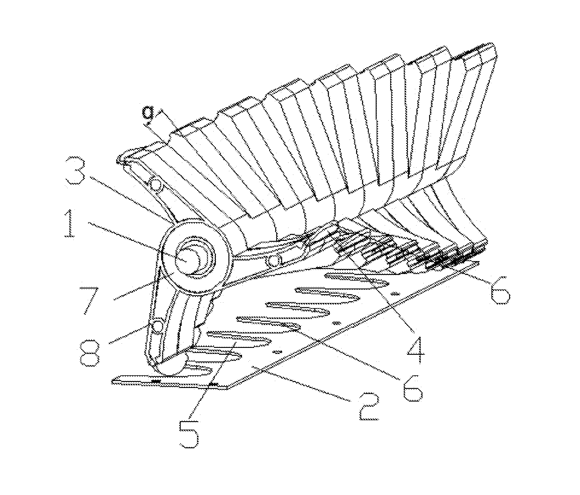
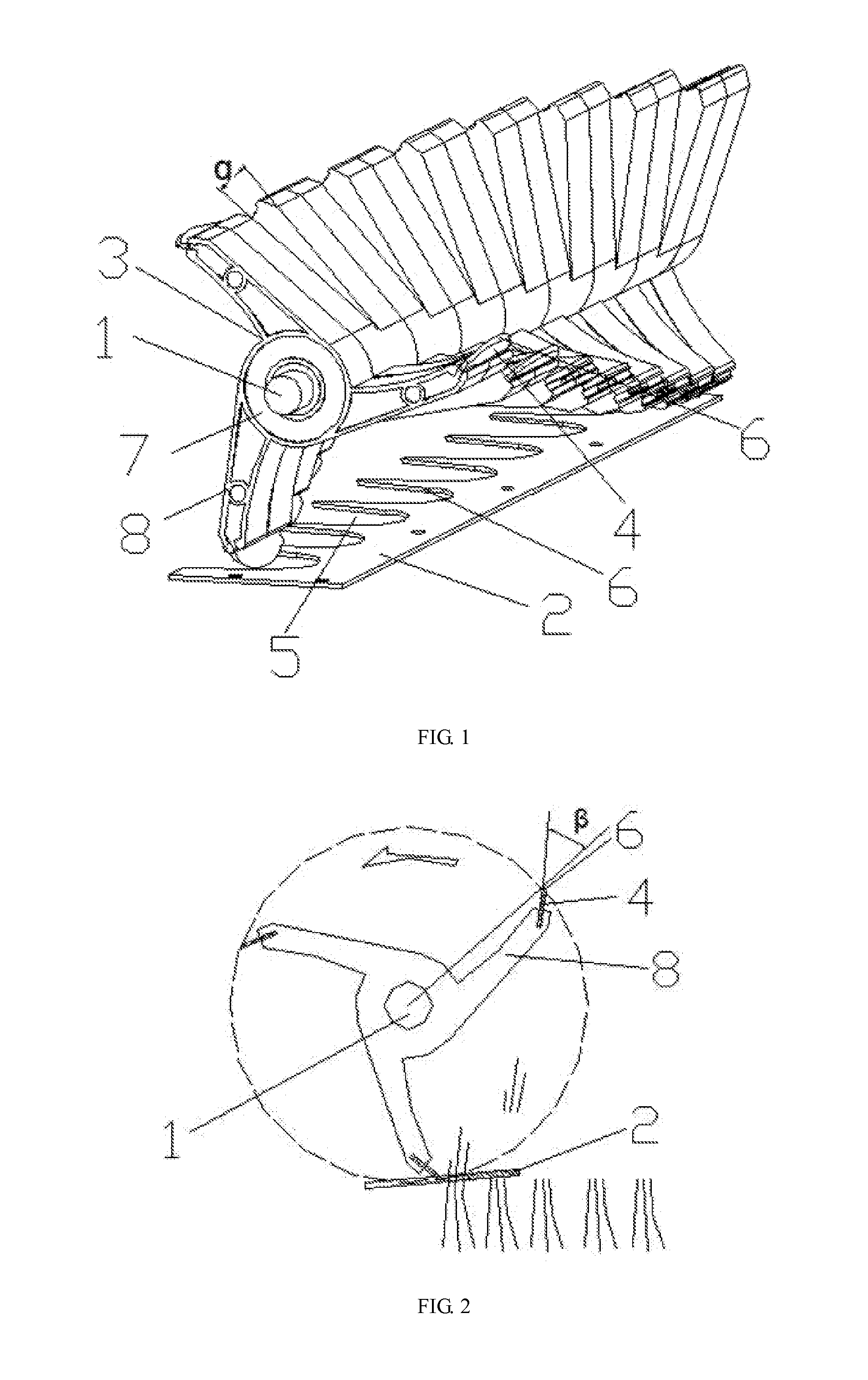
[0021]FIG. 1 and FIG. 2 illustrate a cutting device, comprising a driving axle 1 and a first blade 2, wherein the driving axle 1 and the first blade 2 are fitted on the cutter. The driving axle 1 is fitted with more than 8 blade holding frames 3, each of the blade holding frame 3 is fitted with a second blade 4, the first blade 2 is made with cutting notches 5, the second blade 4 and the cutting notches 5 are made with cutting planes 6. The second blade 4 has an arc shape and the first blade 2 is made with arc-like cutting notches matching the arc-like second blade.
[0022]The blade holding frame 3 comprises a holding axis 7, the holding axis 7 is fitted with blade mounts 8, each of the blade mounts 8 is fitted with a second blade 4, and the blade mounts 8 on the two adjacent holding frames 3 on the blade mount 8 form an angle α of 12°. The holding axis 7 is fitted with three blade mounts 8 at equal intervals. The included angle β between the extension line of the drive axle 1's radiu...
embodiment 2
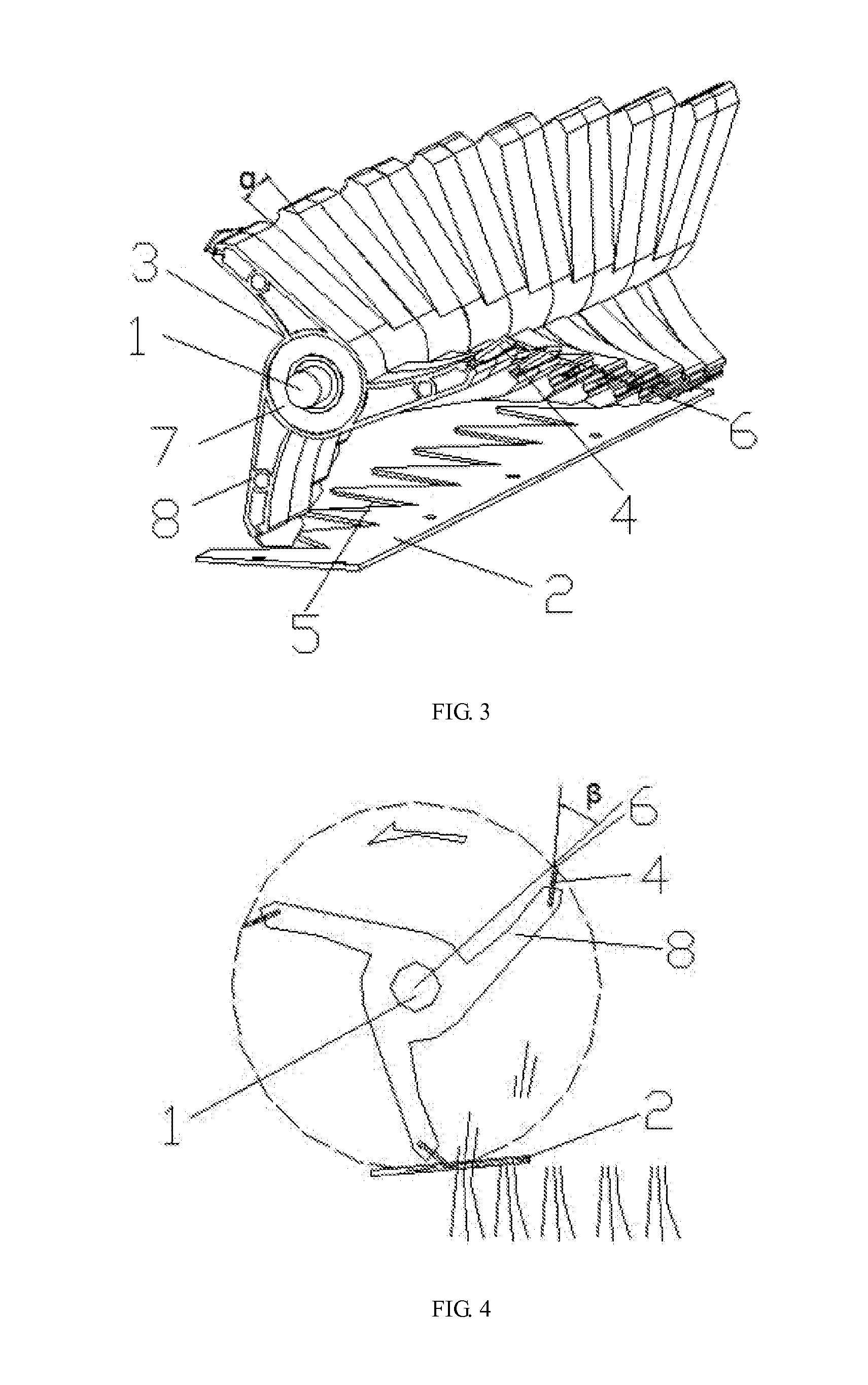
[0025]FIG. 3 and FIG. 4 illustrate a cutting device, comprising a driving axle 1 and a first blade 2, wherein the driving axle 1 and the first blade 2 are fitted on the cutter. The driving axle 1 is fitted with more than 8 blade holding frames 3, each of the blade holding frame 3 is fitted with a second blade 4, the first blade 2 is made with cutting notches 5, and the second blade 4 is made with a cutting plane 6. The second blade 4 has a triangle shape and the first blade 2 is made with triangle-like cutting notches matching the triangular second blade.
[0026]The blade holding frame 3 comprises a holding axis 7, the holding axis 7 is fitted with blade mounts 8, each of the blade mounts 8 is fitted with a second blade 4, and the blade mounts 8 on the two adjacent holding frames 3 form an angle α of 30°. The holding axis 7 is fitted with three blade mounts 8 at equal intervals. The angle β between the extension line of the drive axle 1's radius and the second blade 4 is 35°.
[0027]Dur...
embodiment 3
[0029]FIG. 5 and FIG. 6 illustrate a cutting device, comprising a driving axle 1 and a first blade 2, wherein the driving axle 1 and the first blade 2 are fitted on the cutter. The driving axle 1 is fitted with more than 8 blade holding frames 3, each of the blade holding frame 3 is fitted with a second blade 4, the first blade 2 is made with cutting notches 5, and each of the second cutting notches 5 is made with a cutting plane 6. The second blade 4 has a rectangle shape and the first blade 2 is made with rectangle-like cutting notches matching the rectangle-like second blade.
[0030]The blade holding frame 3 comprises a holding axis 7, the holding axis 7 is fitted with blade mounts 8, each of the blade mounts 8 is fitted with a second blade 4, and the blade mounts 8 on the two adjacent holding frames 3 form an angle α of 60°. The holding axis 7 is fitted with three blade mounts 8 at equal intervals. The angle β between the extension line of the drive axle 1's radius and the second ...
PUM
 Abstract
Description
Claims
Application Information