Apparatus To Extract Magnetic Particles From Suspensions

Inactive Publication Date: 2011-08-18
SHARPE ANTHONY N
View PDF1 Cites 3 Cited by
  • Summary
  • Abstract
  • Description
  • Claims
  • Application Information

AI Technical Summary

Benefits of technology

[0011]The present invention provides a system to rapidly sediment and concentrate relatively large samples of IMPs for easy collection. The apparatus comprises a vessel for containing sample fluid having an inner base surface that slopes downwards towards a collection region, said collection region including a retrieval well for collecting magnetic particles; a magnet assembly for positioning under and in proximity with the vessel for attracting magnetic particles to the base surface of

Problems solved by technology

This small volume results in a limit on the detectable quantity or concentration of target analyte that is often too high for the requirements.
However as no known technique can detect such a target analyte until it has been removed from the test sample into liquid suspension the first step in any analysis would be to shake or blend the 25 g sample with 225 mL of sterile diluent.
The single cell the analysis must detect may now be anywhere in the 250 mL volume of sample-plus-diluent and the probability of capturing it in even a 10 mL aliquot by means of IMPs will be unacceptably low.
This time delay is a serious impediment to rapid analysis.
Assembling its tubes and vessels and removing the captured IMP pellet for introduction to the detection step of an analysis is inconvenient and time consuming.
While this device may be useful in a research laboratory, it has numerous shortcomings that make it quite unsuited for routine use in analytical laboratories.
Fo

Method used


Image

  • Apparatus To Extract Magnetic Particles From Suspensions
  • Apparatus To Extract Magnetic Particles From Suspensions
  • Apparatus To Extract Magnetic Particles From Suspensions

Examples


Example

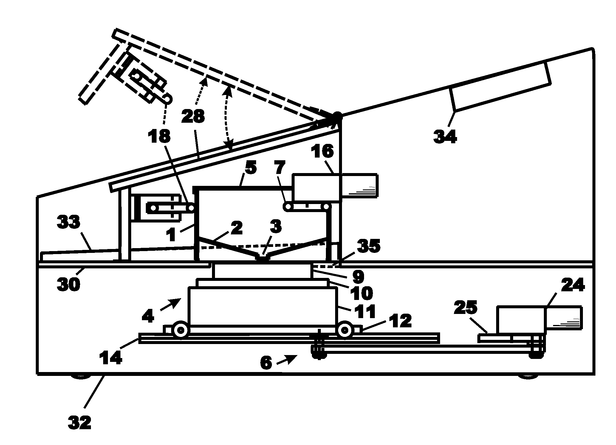
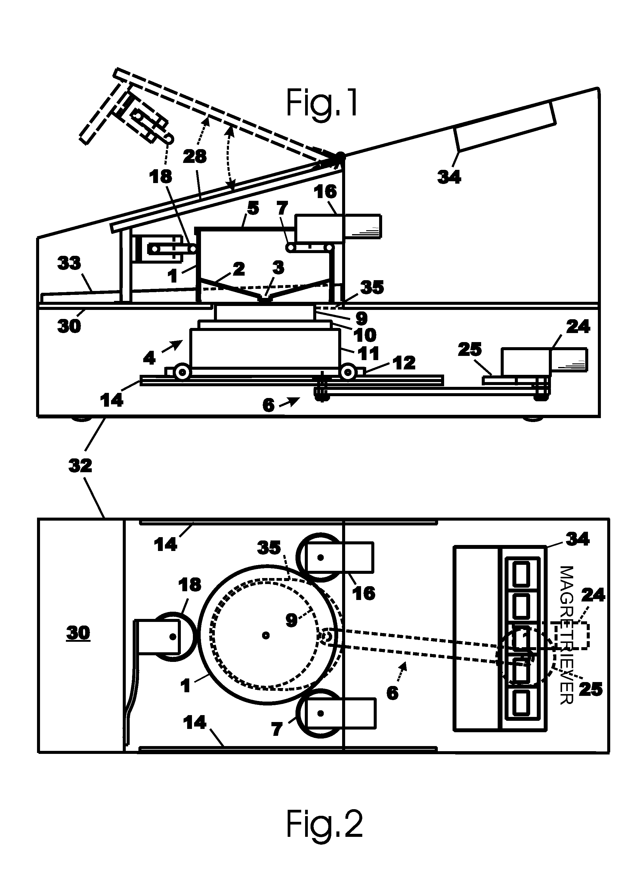
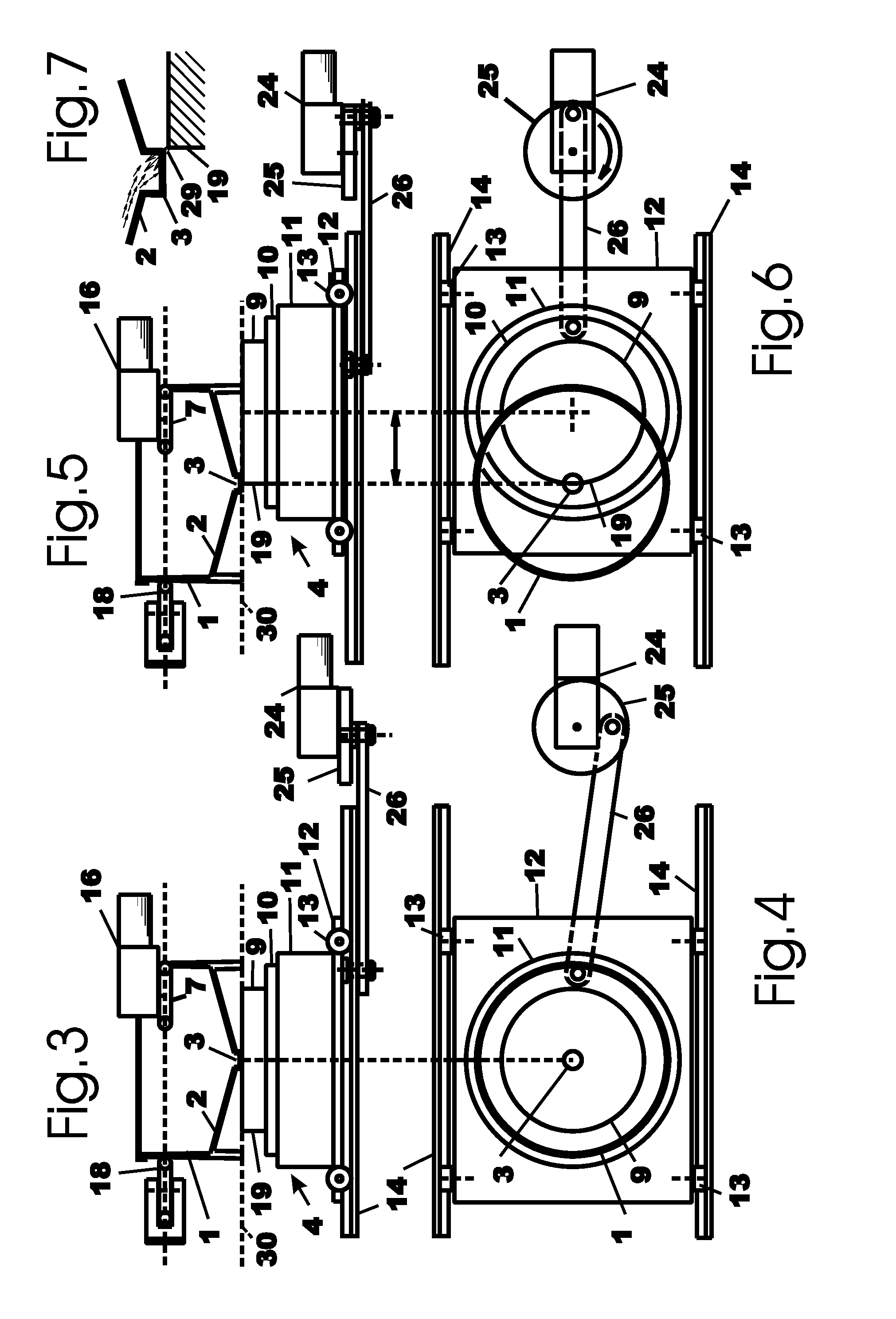
[0026]With reference to FIGS. 1 and 2, the apparatus of the present invention comprises a vessel 1 for containing sample fluid having an inner base surface 2 that slopes downwards towards a well 3, in the form of a cavity in the base 2, for collecting magnetic particles. Positioned under and in proximity with the vessel 1 is a magnet assembly 4 for attracting magnetic particles to the bottom surface of the vessel towards the well. As detailed below, the magnet assembly is arranged to provide a relatively larger magnetic flux density at a peripheral region thereof.

[0027]The magnet assembly 4 is shown laterally movable relative to the vessel 1 by magnet traversing / positioning means 6 adapted to move the magnet assembly 4 relative to the vessel 1 between a first position whereby the magnet assembly 4 is generally centered under the vessel 1, and a second position whereby the peripheral portion of the magnet is positioned under the well 3 of the vessel 1, as shown in FIG. 5 and detailed...


PUM

PropertyMeasurementUnit
Diameteraaaaaaaaaa
Magnetismaaaaaaaaaa
Magnetic permeabilityaaaaaaaaaa

Abstract

A system for concentrating magnetic particles suspended in a fluid comprising a vessel for containing said fluid having an inner base surface that slopes downwards towards a collection region, the collection region including a retrieval well for collecting magnetic particles; a magnet assembly for positioning under and in proximity with the vessel for attracting magnetic particles to the bottom surface of the vessel, said magnet assembly providing a relatively larger magnetic flux density at a peripheral region thereof; means for laterally traversing the magnet assembly relative to the vessel between a first position whereby the magnet is generally centered under the vessel and a second position whereby the peripheral portion of the magnet is positioned under the well of the vessel; and agitation means for agitating said vessel to facilitate movement of the magnetic particles to the well, where the concentrated particles can be easily removed. The system facilitates analysis of relatively large volume samples.

Description

BACKGROUND OF THE INVENTION [0001]1. Field of the Invention[0002]This invention relates to an apparatus for extracting magnetic particles suspended in a fluid, and particularly for sedimenting and concentrating immunomagnetic particles for analysis.[0003]2. Description of Prior Art[0004]The general technology of using antibody-coated magnetic beads or other magnetic particles, hereinafter referred to as immunomagnetic particles or IMPs, to selectively separate and capture analytes from foods or other samples is known as immunomagnetic separation (IMS) and is widely used. In a typical IMS procedure IMPs are suspended in a suspension of the test sample for a time sufficient for them to selectively bind the target analyte and are then pulled out of the suspension as a small pellet-like sediment by means of a strong magnet. After pouring or pipetting away the supernatant suspension the IMPs can be rinsed by resuspending the pellet in clean diluent and resedimenting it with the magnet, a...

Claims


Application Information

Patent Timeline
IPC IPC(8): B03C1/02
CPCB03C1/288B03C2201/26B03C2201/18
Inventor SHARPE, ANTHONY N.
Owner SHARPE ANTHONY N
Why Eureka
Try Eureka