Image forming apparatus and method of controlling the same

a technology of image forming apparatus and density sensor, which is applied in the direction of electrographic process apparatus, instruments, optics, etc., can solve the problems of affecting the accuracy of color balance correction, changing density or chromaticity, and affecting color balance, so as to suppress an increase in the consumption of printing media and toner, and more reliable detection of patches

Active Publication Date: 2009-06-18
CANON KK
View PDF5 Cites 16 Cited by
  • Summary
  • Abstract
  • Description
  • Claims
  • Application Information

AI Technical Summary

Benefits of technology

[0013]The present invention enables realization of more reliable detection of patches formed on a recording medium while suppressing an increase in the consumption of printing media and toners.

Problems solved by technology

Especially in an image forming apparatus using electrophotographic method, only a very small environmental variation may change the density or chromaticity and disturb the color balance.
That is, the density control using the density sensor cannot cope with these changes.
If this situation occurs, the color balance correction accuracy degrades.
This leads to a waste of printing media and toners.
Hence, the number of patches per recording medium decreases, and printing media and toners are consumed in large quantities at the time of color balance correction.

Method used


Image

  • Image forming apparatus and method of controlling the same
  • Image forming apparatus and method of controlling the same
  • Image forming apparatus and method of controlling the same

Examples


Embodiment Construction

[0030]Preferred embodiments of the present invention will now be described in detail with reference to the drawings. It should be noted that the relative arrangement of the components, the numerical expressions and numerical values set forth in these embodiments do not limit the scope of the present invention unless it is specifically stated otherwise.

[0031]

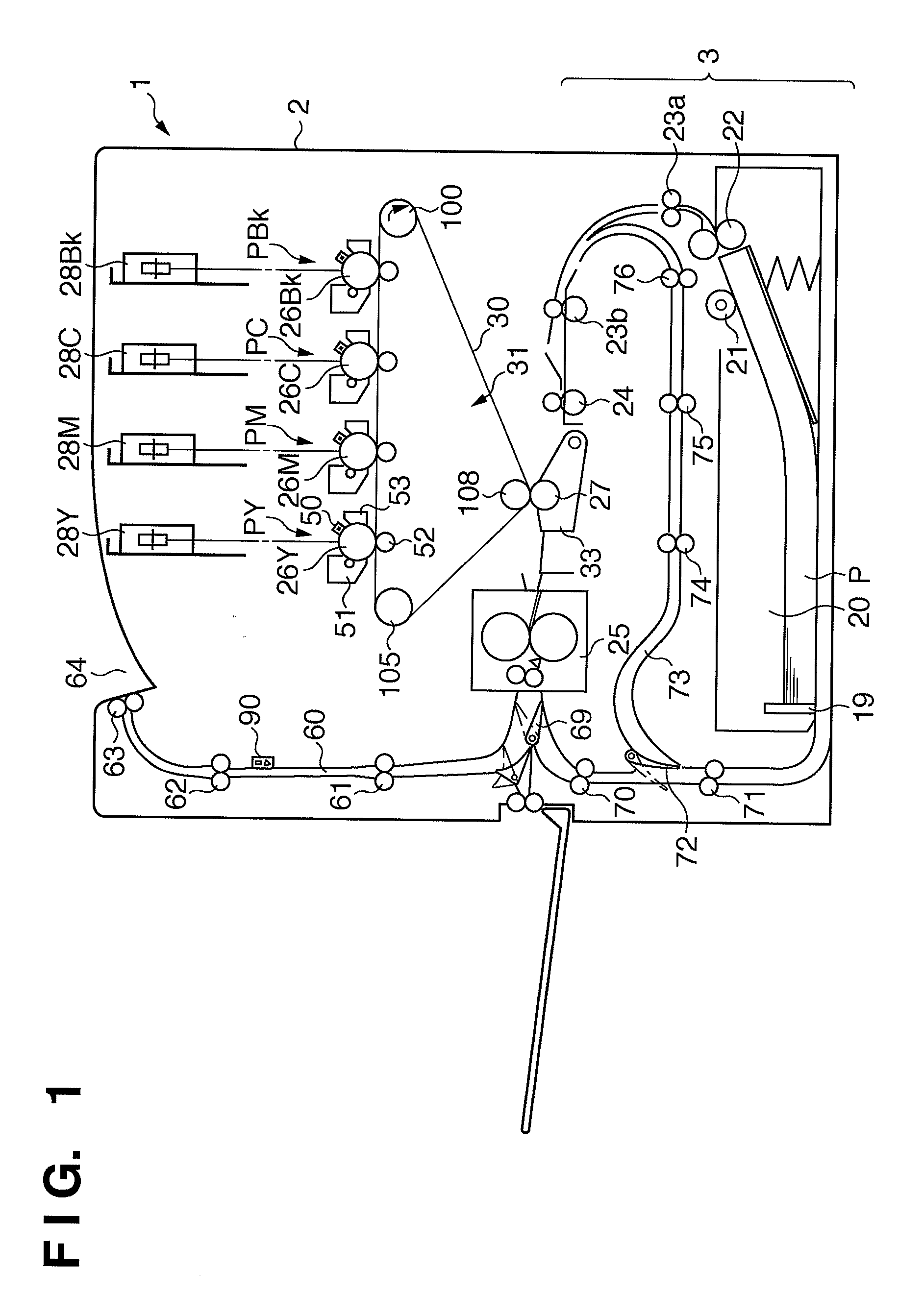
[0032]The arrangement of a printer 1 according to this embodiment will be described with reference to FIG. 1. FIG. 1 is a sectional view showing the arrangement of the printer 1 according to this embodiment. The printer 1 will be explained here as, out of image forming apparatuses using an electrophotographic method, a 4-drum full-color image forming apparatus using an intermediate transfer belt.

[0033]Referring to FIG. 1, reference numeral 2 denotes an apparatus main body that is the main body of the printer 1. Process cartridges P (PY, PM, PC, and PBk) of four colors, that is, yellow (Y), magenta (M), cyan (C), and black (Bk) ar...


PUM


Abstract

This invention provides an image forming apparatus capable of more reliably detecting patches formed on a recording medium while suppressing an increase in the consumption of printing media and toners. In an image forming apparatus which detects the density or color of each patch of a patch array fixed on a recording medium that is conveyed and corrects an image formation condition based on the detection result, the patches are formed as the patch array so that the conveyance-direction length of each patch gradually increases in an order of detection by the patch detection unit, and the conveyance-direction length of each patch gradually increases according to increasing of a detection position variation amount of a patch in the order of detection by the patch detection unit.

Description

BACKGROUND OF THE INVENTION[0001]1. Field of the Invention[0002]The present invention relates to an image forming apparatus for forming an image on a recording medium, and a method of controlling the same.[0003]2. Description of the Related Art[0004]An image forming apparatus such as a printer or a copying machine using an electrophotographic method or an inkjet method is recently required to output a high-quality image. Particularly important factors that determine the quality of an output image are the tone of density and its stability. However, the density or chromaticity of an output image of an image forming apparatus varies due to the variable factors of units in the apparatus concerning environmental changes or long-time use. Note that “chromaticity” in this specification is a general term for information quantitatively representing a color. Chromaticity may be expressed as “color information” or “color value”, or simply as “color”. As a parameter to quantitatively represent ...

Claims


Application Information

Patent Timeline
Patent Type & Authority Applications(United States)
IPC IPC(8): G03G15/00
CPCG03G15/5062G03G2215/0161G03G2215/00067
Inventor KAWAGUCHI, HIROSHI
Owner CANON KK
Why Eureka
Try Eureka