
Blood Collection Device with Tube Retaining Structure

a technology of blood collection device and retaining structure, which is applied in the field of medical fluid transfer device, can solve the problems of blood spillage, tube breakage, slow or stop the blood flow into the blood collection tube,

Inactive Publication Date: 2009-06-18
TYCO HEALTHCARE GRP LP
View PDF23 Cites 29 Cited by
  • Summary
  • Abstract
  • Description
  • Claims
  • Application Information

AI Technical Summary

Benefits of technology

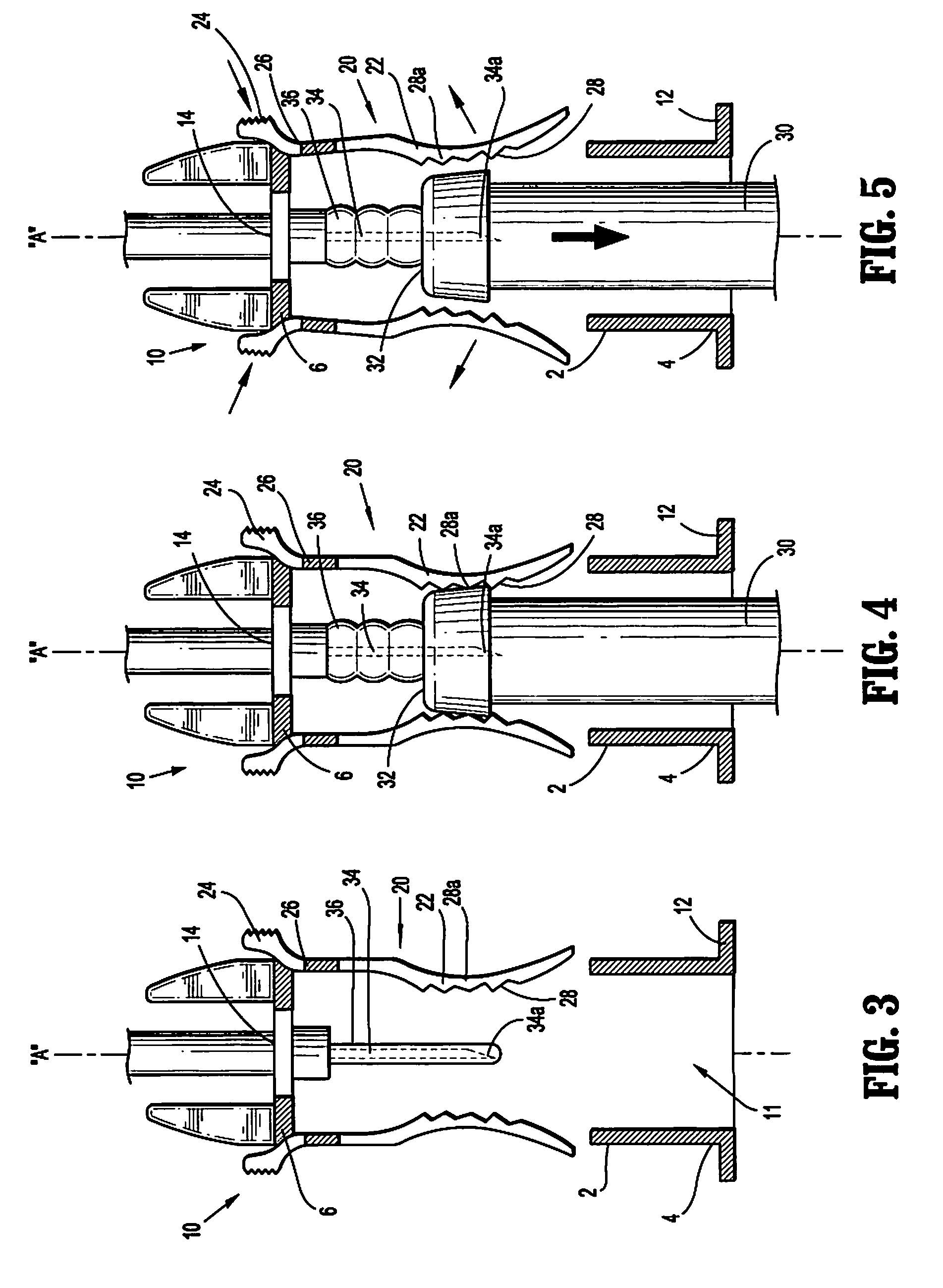
[0011]In one embodiment, the retaining structure includes at least one finger nub. Each of the at least one finger nubs is connected to one of the at least one arms by a pivot member and is actuable to disengage the at least one arm from engagement with a blood collection tube positioned within the receptacle of the body. The retaining structure may include one or more teeth which are configured to engage the blood collection tube.
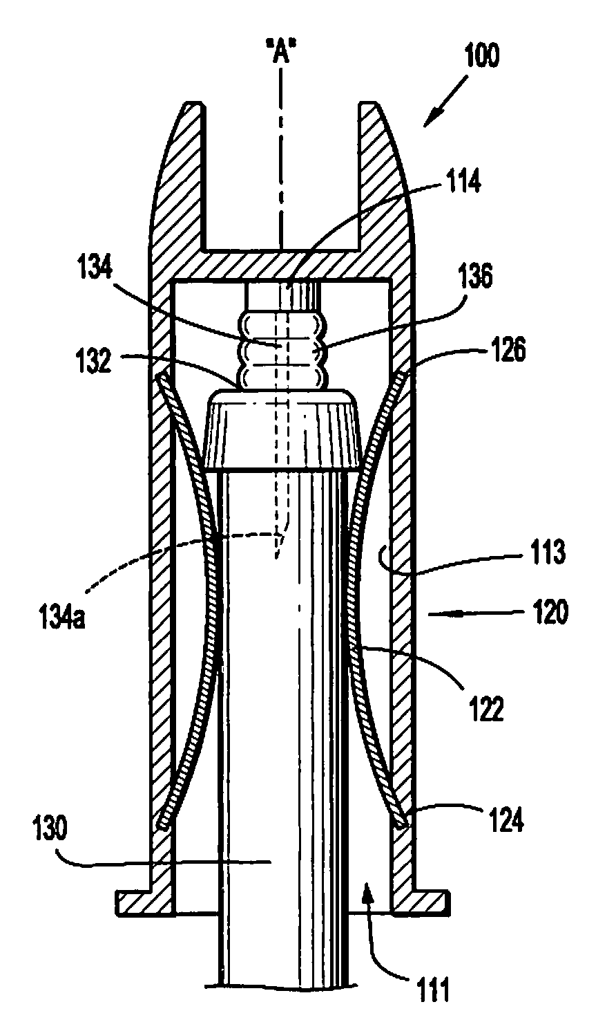
[0012]In one embodiment, the retaining structure is supported on an inner surface of the body defining the receptacle. The retaining structure may include at least one resilient biasing member disposed on an inner surface of the body. The at least one resilient biasing member has first and second ends secured to the inner surface of the body such that a central portion of the at least one resilient biasing member bows inwardly from the inner surface of the body into the receptacle.

Problems solved by technology

When the valve member is in a compressed state, the valve member tends to urge the blood collection tube from the receptacle of the blood collection device, which results in slowing or stopping the blood flow into the blood collection tube.
If a blood collection tube were to become disengaged from a blood collection device, it is likely that the tube would break and blood would be spilled exposing medical personnel to the dangers of BBP's and also broken glass.

Method used


Image

  • Blood Collection Device with Tube Retaining Structure
  • Blood Collection Device with Tube Retaining Structure
  • Blood Collection Device with Tube Retaining Structure

Examples


Embodiment Construction

[0026]Embodiments of the presently disclosed medical device will now be described in detail with reference to the drawings wherein like reference numerals designate identical or corresponding elements in each of the several views. In the discussion that follows, the term “proximal” refers to a portion of a structure that is closer to a user, and the term “distal” refers to a portion that is further from the user.

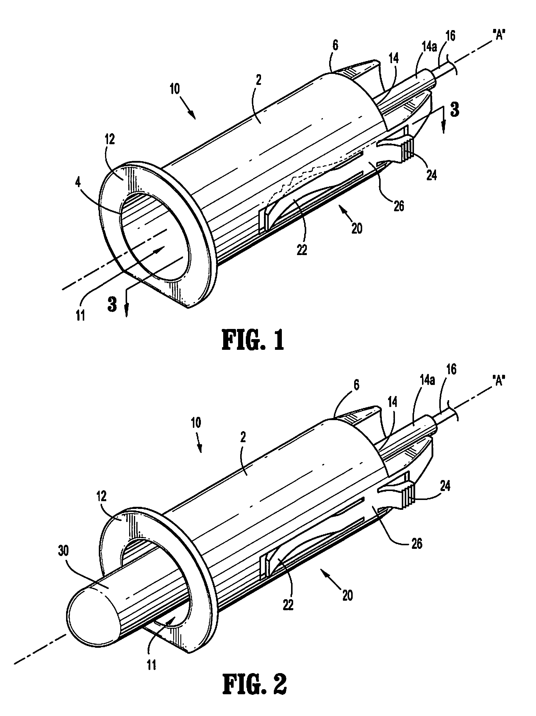
[0027]Referring initially to FIGS. 1-5, a medical blood collector is provided, which includes a blood collection device 10 having a substantially tubular housing 2 defining a receptacle 11. Housing 2 includes a proximal open end 4 and a distal end 6 having a hub 14 disposed thereon. A finger flange 12 is provided on the proximal end 4 of housing 2 to facilitate insertion of a blood collection tube 30 into receptacle 11. Proximal open end 4 is configured and dimensioned to allow a blood collection tube 30 to be inserted therethrough.

[0028]Hub 14 defines a channel (not shown) ...


PUM


Abstract

A blood collection device is disclosed which includes a body defining a receptacle dimensioned to receive a blood collection tube. The body has a first open end and a second end supporting a needle having a proximal end extending into the receptacle and a distal end extending distally of the body. Retaining structure is supported on the body. The retaining structure extends into the receptacle and is configured to releasably retain the blood collection tube within the receptacle.

Description

CROSS-REFERENCE TO RELATED APPLICATIONS[0001]The present application claims the benefit of and priority to U.S. Provisional Patent Application No. 61 / 007,639, filed on Dec. 14, 2007, which is incorporated herein by reference in its entirety.BACKGROUND[0002]1. Technical Field[0003]The present disclosure relates to the field of medical fluid transfer devices and, more particularly, to devices for safely transferring bodily fluids to a receptacle.[0004]2. Description of Related Art[0005]In the medical field, fluid transfer devices, particularly, blood collection devices are used to draw blood from patients for blood tests and other medical procedures. At all times, phlebotomists have to be careful of the being exposed to life-threatening bloodborne pathogens (BBP) such as HIV and hepatitis.[0006]Blood collection devices are well known in the medical field and typically include a body defining a receptacle which is dimensioned to receive a blood collection tube. The body includes an ope...

Claims


Application Information

Patent Timeline
Patent Type & Authority Applications(United States)
IPC IPC(8): A61B5/15
CPCA61B5/1438A61B5/1405A61B5/15003A61B5/150389A61B5/150473A61B5/150572A61B5/150732A61B5/154A61B5/1444A61B5/15
Inventor NOBLE, MICHAEL J.CHELAK, TODD M.
Owner TYCO HEALTHCARE GRP LP
Learn More