Removable hard drive casing

a hard drive and casing technology, applied in the direction of electrical apparatus casings/cabinets/drawers, furniture parts, instruments, etc., can solve the problem that hard drive b>14/b> cannot be successfully coupled to the computer, and achieve the effect of easy push into the receiving spa

Inactive Publication Date: 2009-06-25
CAMEO COMM
View PDF6 Cites 44 Cited by
  • Summary
  • Abstract
  • Description
  • Claims
  • Application Information

AI Technical Summary

Benefits of technology

[0008]The second objective of the present invention is to provide a removable hard drive casing which uses a protective cover to hide the removable hard drive casing itself in a computer case when installed, with the aims of beautification and dust prevention.
[0011]In a preferred embodiment, the protective cover comprises a resilient fastener on an upper edge thereof for fastening the protective cover to the fixing frame and providing a force-exertion point so that the hard drive tray can be easily pulled out of or pushed into the receiving space of the fixing frame.
[0012]In a preferred embodiment, a bottom of the receiving space of the fixing frame is formed with a framework of crisscrossing bars, and the framework has a lead angle at an end thereof where the opening is located, so that the hard drive tray can be easily pushed into the receiving space. The hard drive tray is provided with a plurality of apertures at a bottom thereof, so that heat generated by the hard drive can be discharged through the apertures and pass through openings formed in the framework to go outward the fixing frame.

Problems solved by technology

Therefore, the position of the hard drive tray 12 after being inserted into the base 11 tends to vary, resulting in a positional mismatch of pins and pinholes between the end of the hard drive 14 and the connection port 15 at the end of the base 11, so that the hard drive 14 cannot be successfully coupled to the computer.

Method used


Image

  • Removable hard drive casing
  • Removable hard drive casing
  • Removable hard drive casing

Examples


Embodiment Construction

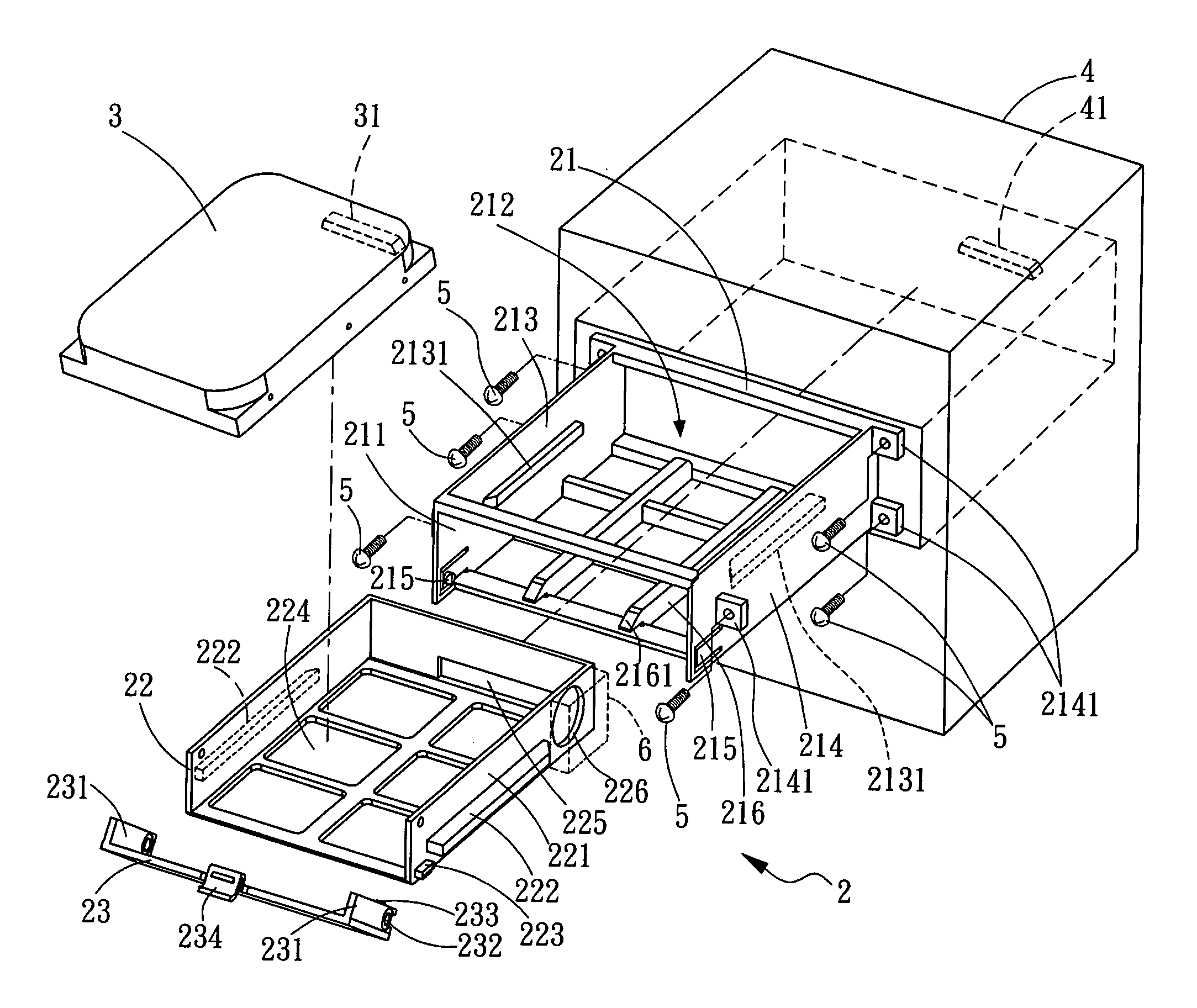
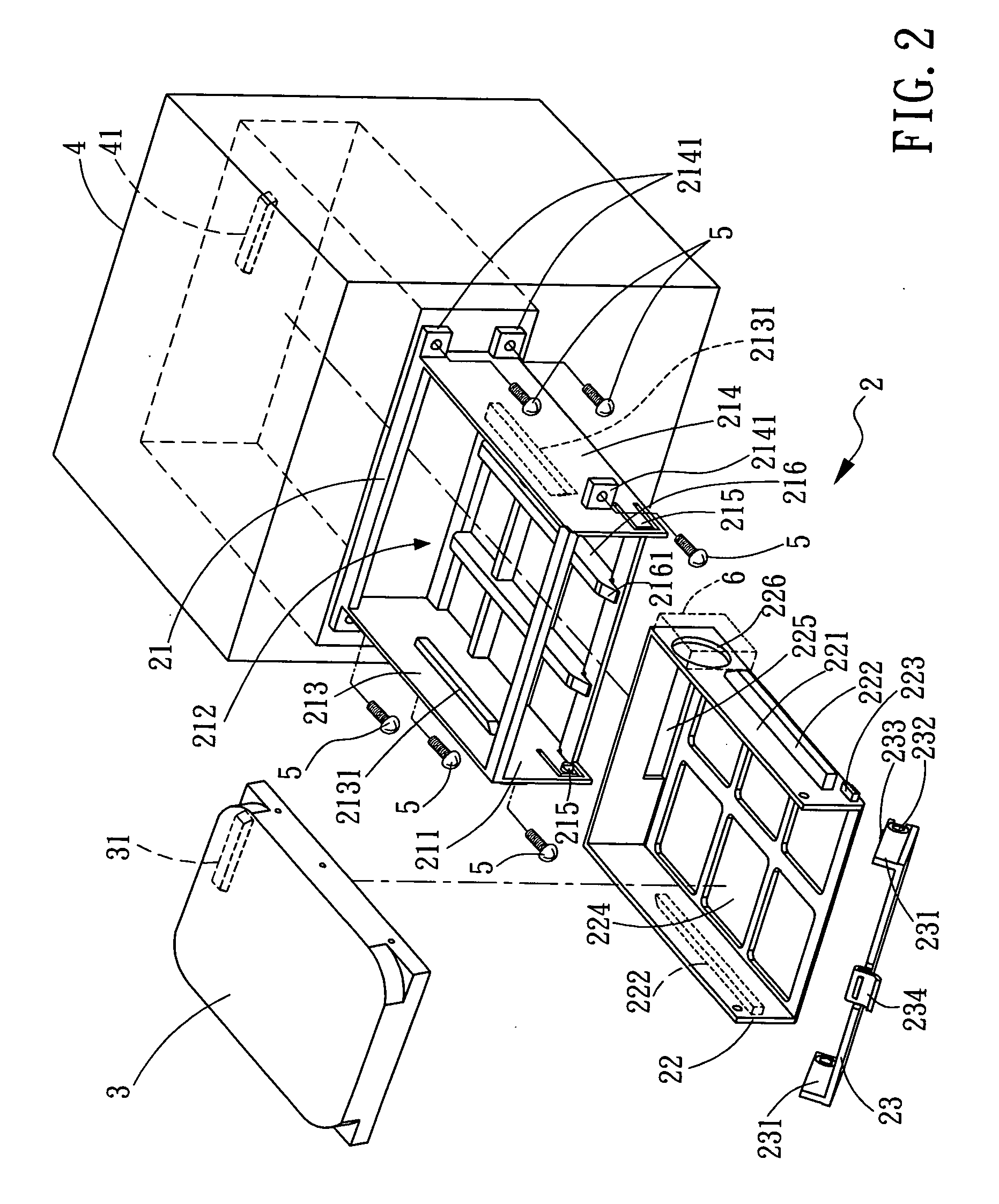
[0023]FIG. 2 is an exploded view of a removable hard drive casing according to the present invention. As shown in FIG. 2, a removable hard drive casing 2 is provided for rapidly integrating a hard drive 3 into a computer case 4. The removable hard drive casing 2 comprises a fixing frame 21, a hard drive tray 22 and a protective cover 23.

[0024]The fixing frame 21 is a hollow frame with an opening 211 and can be installed in the computer case 4 so that the opening 211 is generally flush with a front surface of the computer case 4. At the center of the fixing frame 21 is an open receiving space 212, whose two opposite inner sidewalls 213 are each provided with a rib 2131. A plurality of fixing tabs 2141 are positioned on each of the two opposite outer sidewalls 214 of the fixing frame 21, so that the fixing frame 21 can be attached to the computer case 4 with a plurality of screws 5. The outer sidewalls 214 on the two sides of the opening 211 are each formed with a resilient pivot end ...


PUM


Abstract

A removable hard drive casing for rapidly integrating a hard drive into a computer case, comprising a fixing frame, a hard drive tray and a protective cover. The fixing frame comprises an opening and a receiving space. The hard drive tray can hold the hard drive therein and be inserted and integrated into the receiving space through the opening of the fixing frame. The hard drive tray is provided with a rack on one of the outer sidewalls thereof. The protective cover is a plate-like cover and has two opposite axle ends on the sidewalls thereof, pivotally connected to the opening of the fixing frame. The protective cover further has an arcuate rack corresponding to the rack provided on the outer sidewall of the hard drive tray. The hard drive tray can be moved for a predetermined distance to and from the inside of the fixing frame by means of the arcuate rack on the protective cover driving the rack on the hard drive tray when the protective cover is opened and closed.

Description

BACKGROUND OF INVENTION[0001]1. Field of the Invention[0002]The present invention relates to a removable hard drive casing, and more particularly, to a removable hard drive casing in which a hard drive tray with a hard drive supported thereon can be pulled out a predetermined distance from a fixing frame when a protective cover is opened, so that the hard drive is simultaneously disengaged from a connection port in a computer case to facilitate retrieving of the hard drive.[0003]2. Description of the Prior Art[0004]FIG. 1 is a schematic sectional view of a conventional removable hard drive casing 1 comprising a base 11, a hard drive tray 12 and a handle 13. The base 11 is fixedly attached to a pre-built drive bay of a computer case. The hard drive tray 12 can hold a hard drive 14 so that the hard drive 14 can be inserted into the base 11 by means of the hard drive tray 12 and then coupled to a connection port 15 at one end of the base 11, so as to be electrically connected to the co...

Claims


Application Information

Patent Timeline
Patent Type & Authority Applications(United States)
IPC IPC(8): H05K5/00A47B81/00
CPCG11B17/0407G11B33/124G11B33/122G11B33/027
Inventor YANG, CHING LUN
Owner CAMEO COMM
Why Eureka
Try Eureka