Motion detector for detecting tampering and method for detecting tampering

a motion detector and detector technology, applied in the field of detectors, can solve the problems of detectors having inherent weakness to paint applied with brushes, transient change, and affecting the detection functionality of motion detection in a protected area

Inactive Publication Date: 2009-07-02
HONEYWELL INT INC
View PDF5 Cites 28 Cited by
  • Summary
  • Abstract
  • Description
  • Claims
  • Application Information

AI Technical Summary

Benefits of technology

The detector and method described in this patent can be used for various purposes such as a safety system or even just detecting objects in general. This allows for more flexibility and versatility when utilizing these technologies.

Problems solved by technology

The technical problem addressed in this patent text relates to identifying a solution that can effectively and reliably prevent unauthorized individuals from deliberately covering up or damaging motion detectors, including those made with advanced technologies like near infrared sensors and microwave sensing systems. Current solutions tend to rely upon detecting small amounts of heat generated through normal activities or temporary fluctuations in the detector's signal, making them unreliable at detecting more serious threats. This patent seeks to address this issue by providing a new approach to identify potential masking agents and mitigate against their effects on motion detection technology.

Method used


Image

  • Motion detector for detecting tampering and method for detecting tampering
  • Motion detector for detecting tampering and method for detecting tampering
  • Motion detector for detecting tampering and method for detecting tampering

Examples


Embodiment Construction

[0018]The present invention now will be described in detail hereinafter with reference to the accompanying drawings, in which exemplary embodiments of the invention are shown. However, this invention may be embodied in many different forms and should not be construed as limited to the embodiments set forth herein. Like numerals refer to like elements throughout.

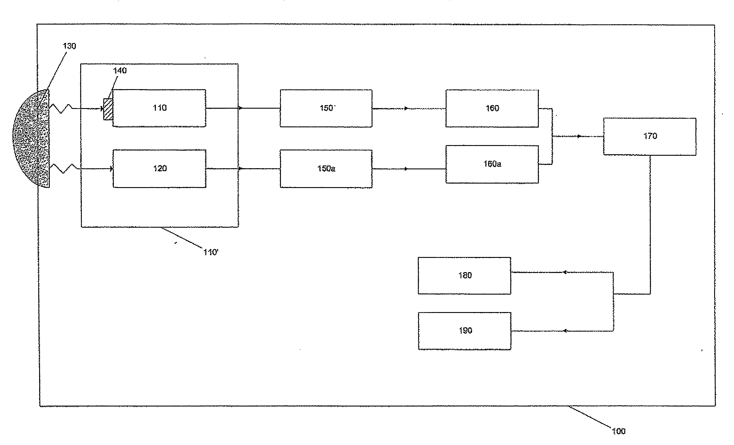
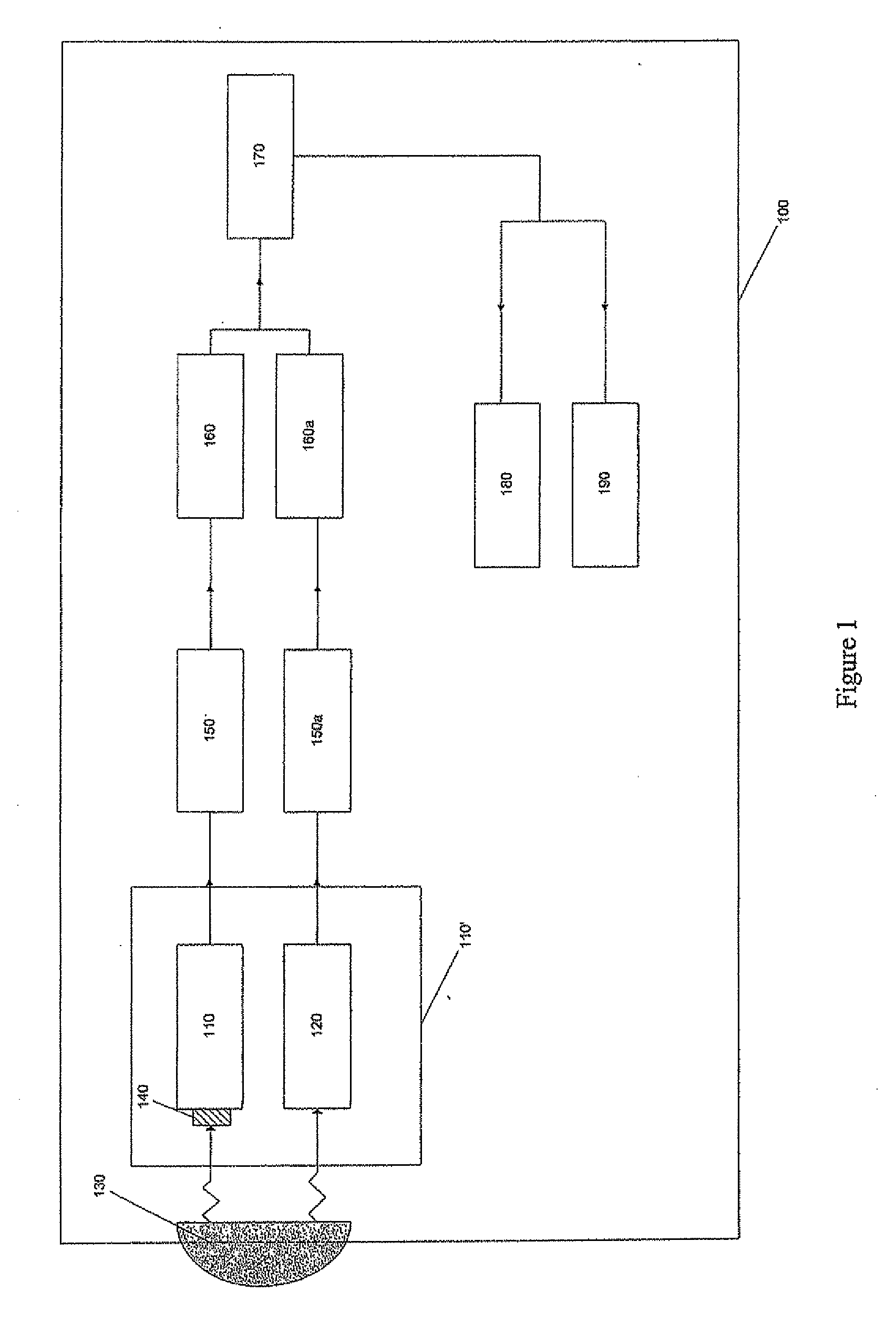
[0019]FIG. 1 illustrates a block diagram of a motion detector 100 according to one exemplary embodiment of the present invention. Generally, the motion detection system 100 includes a pyroelectric sensor 110 containing an optical filter 112, a vibration sensor 120, a lens 130, a first signal amplifier 150 and a second signal amplifier 150a, a first signal filter 160 and a second signal filter 160a, and a processing unit 170. Additionally, the motion detector 100 includes an alarm relay 180 which signals to the control panel when a human is detected. When the control panel is armed, the panel will take measures, such as soundi...


PUM


Abstract

A motion detector for detecting a tampering within a detection zone. A vibration-sensing unit sensitive to vibrations applied to the detector is provided to produce a vibration output signal representative of a detected parameter of the vibrations. A light-sensing unit sensitive to light in a predetermined spectrum is provided to produce a light output signal representative of a detected parameter of the light in the predetermined spectrum. A processing unit is further provided to determine if the vibration output signal is consistent with a predetermined model indicative of a tampering and producing an activating signal accordingly.

Description


Claims


Application Information

Patent Timeline
Owner HONEYWELL INT INC
Why Eureka
Try Eureka