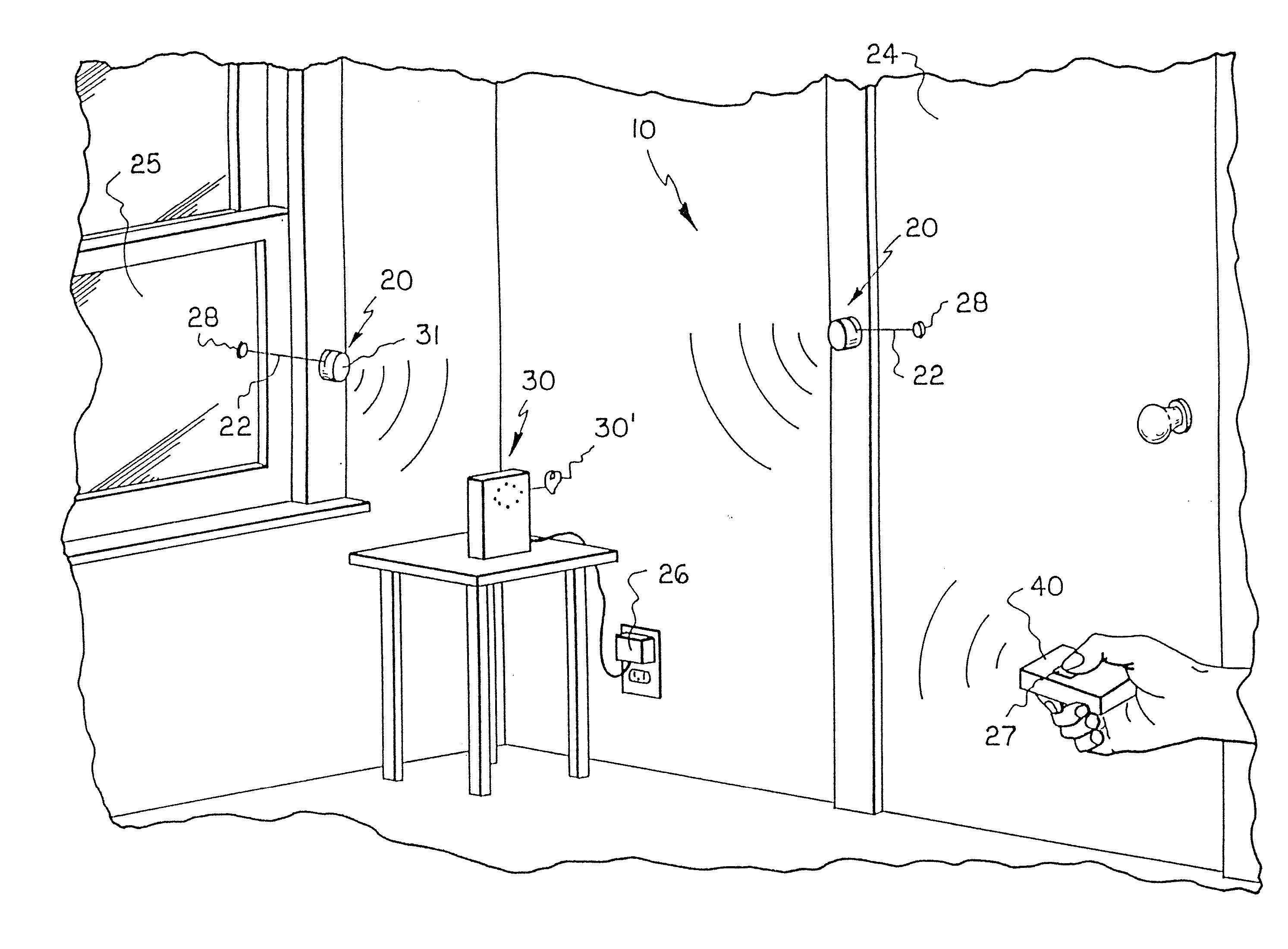
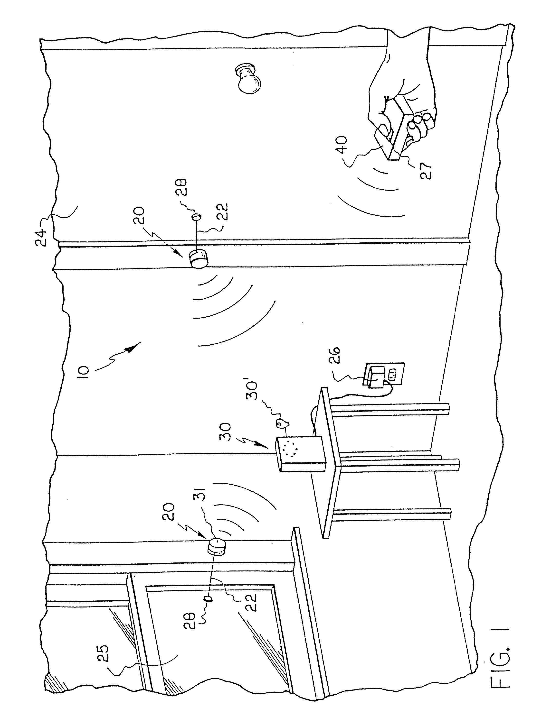
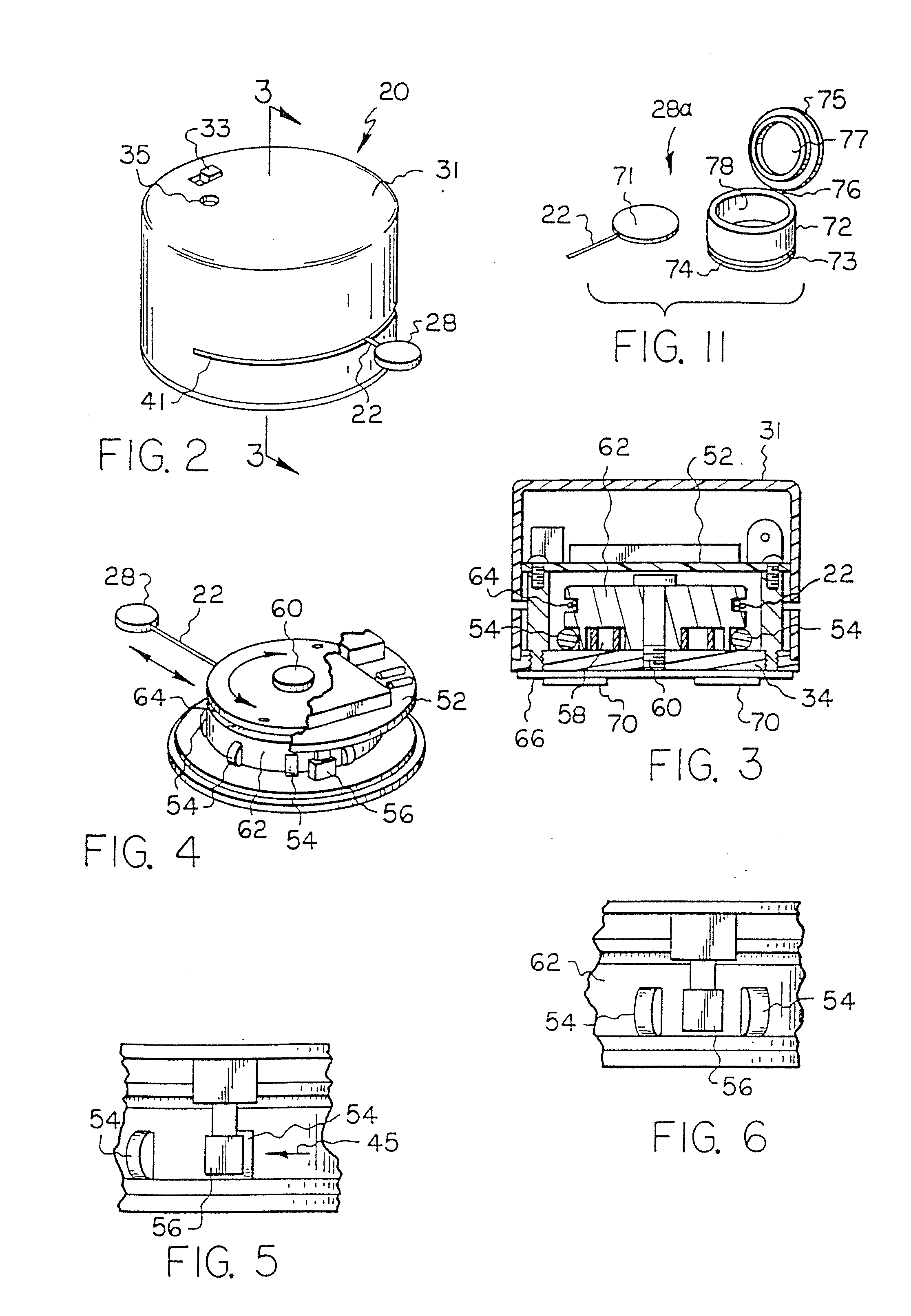
Portable Motion Detector And Alarm System And Method

a motion detector and alarm system technology, applied in the direction of acceleration measurement using interia forces, electric signalling details, instruments, etc., can solve the problems of difficult relocation of sensors of this system, time-consuming and complicated installation of the system, and extensive wiring of the premises, so as to achieve convenient transportation and packing in a suitcase

Inactive Publication Date: 2010-12-02
SCRIPT SECURITY SOLUTIONS
View PDF49 Cites 135 Cited by
  • Summary
  • Abstract
  • Description
  • Claims
  • Application Information

AI Technical Summary

Benefits of technology

[0017]It is a further object of the invention to provide a movement detection and alarm system which is portable and is easily packed in a suitcase and transported wit

Problems solved by technology

The problem of protecting homes, businesses and other premises against unauthorized intrusions is becoming increasingly important due to the increase in vandalism, theft and even physical attacks upon the inhabitants.
While effective, this system requires extensive wiring of the premises as a bus line must be routed about the interior perimeter of the premises between a master control station and the ports of entry at which the motion sensors are to be located.
He

Method used


Image

  • Portable Motion Detector And Alarm System And Method
  • Portable Motion Detector And Alarm System And Method
  • Portable Motion Detector And Alarm System And Method

Examples


second embodiment

[0121]In the remote notification device 92, shown in FIG. 14B, the device, referred to by reference numeral 92B, is a stand-alone unit that does not require the computer 94. It includes a D.C. power supply 120, a memory 122, an RF receiver 124, and a network interface 126. The power supply 120 can be constructed using any suitable constant voltage source, including a rechargeable battery or an AC / DC transformer. A voltage level of 12 Volts should be sufficient to power the remote notification device 92. The memory 122 can be implemented using a conventional RAM or flash memory chip (or plug-in card). A memory capacity of about 4 to 16 MB, expandable to 256 MB or more, should be sufficient for the remote notification device 92. The RF receiver 124 operates at the frequency of the RF transmitter 104 in the information gathering device 90. It is adapted to receive and process either analog or digital transmissions, depending on the nature of the RF transmitter 10. The network interface...

third embodiment

[0122]In the remote notification device 92, shown in FIG. 14C, the device, referred to by reference numeral 92C, comprises various functional devices that plug in as modules to a suitable base interface 130. If the base interface 130 is a computer, the plug-in modules could be implemented as PC or PCMIA cards. Other base interfaces include the DVi family of set top devices from Motorola Corporation. In either case, the plug-in modules could include a memory module 132, an RF receiver module 134, and a network interface module 136. Power for these modules would be typically provided by the base interface 130. The memory module 132 can be implemented using a conventional RAM or flash memory chip (or plug-in card). A memory capacity of about 4 to 16 MB, expandable to 256 MB or more, should be sufficient for the remote notification device 92C. The RF receiver module 134 operates at the frequency of the RF transmitter 104 in the information gathering device 90. It is adapted to receive a...


PUM


Abstract

A portable security alarm system including a movement detecting and signal transmitting member for mounting on or proximate to the object whose movement is to be detected, a signal receiving and alarm generating member for receiving a signal from the movement detecting and signal transmitting member and producing a security response, a remote control for actuating and deactuating the signal receiving and alarm generating member, an environmental monitoring member for sensing an environmental condition and providing a signal to the signal receiving and alarm generating member, a visual information gathering member for gathering visual information and providing a signal to the signal receiving and alarm generating member, an audio output member for receiving a signal from the signal receiving and alarm generating member and generating an audio output, and components for delivering a security notification to remote recipients. A security network that includes the alarm system is also disclosed. An inertial sensor for alarm system or for activating or deactivating a device is additionally disclosed.

Description

CROSS-REFERENCE TO RELATED APPLICATIONS[0001]This application relates to copending U.S. application Ser. No. 10 / 563,185, which is the national stage of International Application No. PCT / US2004 / 021,371 filed Jul. 2, 2004, which claims the benefit of U.S. application Ser. No. 10 / 613,518 filed Jul. 3, 2003.BACKGROUND OF THE INVENTION[0002]1. Field of the Invention[0003]The invention relates generally to a motion detector and alarm system for actuating an alarm device in response to movement of an object, and more particularly to a portable motion detector and alarm system which is easy to install and operate and is capable of detecting motion relative to a variety of predetermined positions. Still more particularly, the invention concerns an improved inertial sensor that may be used in a motion detector and alarm system.[0004]2. Prior Art[0005]The problem of protecting homes, businesses and other premises against unauthorized intrusions is becoming increasingly important due to the inc...

Claims


Application Information

Patent Timeline
IPC IPC(8): G08B1/08G01P15/09
CPCG01P15/09G08B13/08G08B13/1436G08B25/006G08B25/10G08B25/005G08B25/008
Inventor SCRIPT, MICHAEL H.
Owner SCRIPT SECURITY SOLUTIONS
Why Eureka
Try Eureka