
Multi tier wireless communication system

a wireless communication system and multi-tier technology, applied in the field of communication systems, can solve the problems of large control panel, strict limits on the expansion capacity of each control system, and the wiring into the central control panel becomes more and more complex, so as to achieve the effect of reducing the number of batteries, and reducing the number of devices

Inactive Publication Date: 2006-04-11
HONEYWELL INC
View PDF57 Cites 136 Cited by
  • Summary
  • Abstract
  • Description
  • Claims
  • Application Information

AI Technical Summary

Benefits of technology

"The patent describes a communication system for wireless devices that use low power devices and higher power routers for communication with a central controller. The low power devices can be battery powered and operate at low power levels, while the routers have higher power levels and can communicate with each other and the controller at faster speeds. The system provides flexibility in placement of devices and can be used for security, control, and monitoring purposes. The use of low power transceivers and multiple routers allows for more efficient communication and easier integration of devices into existing systems. The system also allows for bidirectional communication and sleep mode for low power devices. Overall, the system provides a cost-effective and flexible solution for monitoring and controlling assets in structures or areas."

Problems solved by technology

However, as the number of devices in such systems increases, the wiring into the central control panel becomes more and more complex.
Physical connections must be provided for devices to be added, leading to very large control panels, and strict limits on the expansion capacity of each control system.
A further problem associated with hardwired systems is that devices may be added following completion of construction of a structure, but may require a crew of workers taking many hours, either tearing into walls to add wiring, or the use of additional devices utilizing radio frequency “RF” transmission capability.
It is also difficult to integrate new, higher function devices which require high bandwidth data transmission capabilities.
Two way communication may also not be provided by existing wired systems.
Installing a new system in an existing structure can require significant structure invasive and labor intensive wiring done by a work crew causing much disruption of the use of the structure.
Thus, the use of either wired and wireless devices in such systems can be both costly and inconvenient.
The use of both wired and wireless devices leads to increased complexity and compounds the problems associated with each.
However, as discussed above, one problem in using such devices for systems is that the distance such devices can transmit is limited by the available transmission power.
This has lead to the cost of wireless devices increasing dramatically.
In addition, higher power levels have shortened battery life, which then require replacing more often.
More expensive batteries have somewhat solved this problem, but have dramatically increased the overall cost of the devices.
While some devices can be plugged into AC outlets, they are not always conveniently located.
With larger structures being fitted with systems, the distance between devices and a controller has further exacerbated the transmission distance problem.
Hardwired devices in a mostly wireless system add complexity to the system, further increasing the costs.
Also, since the hardwired devices are only used for the longest distances from the controller, the inconvenience and expense of wiring increases.
Retrofitting these to existing systems has proven costly.
Making devices with transmitters that can interface into such networks is further increasing the overall cost of the devices.

Method used


Image

  • Multi tier wireless communication system
  • Multi tier wireless communication system
  • Multi tier wireless communication system

Examples


Embodiment Construction

[0026]In the following detailed description, reference is made to the accompanying drawings which form a part hereof, and in which is shown by way of illustration specific embodiments in which the invention may be practiced. These embodiments are described in sufficient detail to enable those skilled in the art to practice the invention, and it is to be understood that other embodiments may be utilized and that structural, logical and electrical changes may be made without departing from the spirit and scope of the present invention. The following detailed description is, therefore, not to be taken in a limiting sense, and the scope of the present invention is defined by the appended claims.

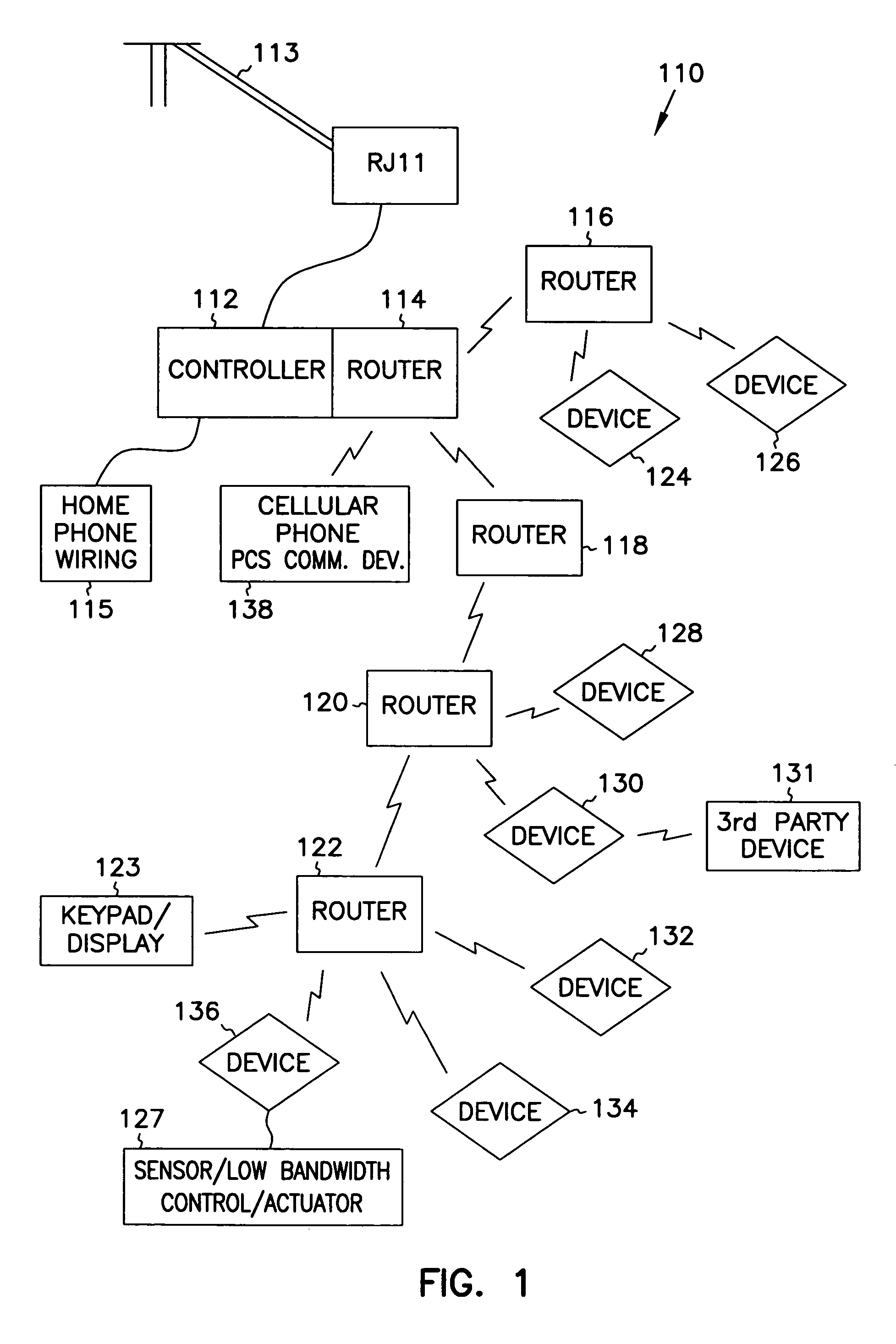
[0027]A two tier communication network infrastructure for providing communication for a system is shown generally at 110 in FIG. 1. The system comprises a controller 112 which may be a personal computer, such as a lap top general purpose computer, or a specially designed ASIC based controller as ...


PUM


Abstract

A monitoring system is provided with a two tier communication network. Multiple first tier nodes comprising wireless or RF sensors are each equipped with transceivers operating at a first, low power level. Multiple second tier nodes are spaced to communicate with selected sensors at the lower bandwidth level, and also communicate with each other at a higher power level and higher bandwidth, to route sensor communications to a central controller. The sensors comprise standard home and small business sensors such as motion detectors, glass breakage, pressure, temperature, humidity and carbon monoxide sensors to name a few, each equipped with a transceiver. The sensors are placed throughout a structure to be protected or monitored. Since such structures can be quite large, several second tier routers are provided such that at least one is within range of each sensor to receive its low power signals. A routing table is dynamically generated to direct communications between routers and the controller

Description

FIELD OF THE INVENTION[0001]The present invention relates to communication systems, and in particular to multi tier communication system for communicating between multiple devices.BACKGROUND OF THE INVENTION[0002]Home and business security, automation, and monitoring systems, and industrial and factory control and communication systems are becoming more and more sophisticated. When installed during the building of a structure such as a house, business office tower factory or warehouse, remote devices, such as sensors, motors, switches and other actuators may be hardwired into a central control panel without much disruption to use of the structure. However, as the number of devices in such systems increases, the wiring into the central control panel becomes more and more complex. Physical connections must be provided for devices to be added, leading to very large control panels, and strict limits on the expansion capacity of each control system.[0003]A further problem associated with...

Claims


Application Information

Patent Timeline
Patent Type & Authority Patents(United States)
IPC IPC(8): H04Q7/00G08B3/10G08B25/00G08B25/10H04L12/28H04L12/56H04L29/06H04L29/08H04M11/04H04W24/00H04W48/08H04W48/16H04W52/02H04W84/18
CPCG01D21/00G08B25/009G08B25/10H04L12/2803H04L12/2827H04L12/2834H04L29/06H04M11/04H04W40/22H04L67/12G08B3/1083Y02B60/50H04L2012/2841H04L2012/2845H04W24/00H04W48/08H04W48/16H04W84/18H04L69/329H04L9/40
Inventor KRIZ, JEFFREY J.
Owner HONEYWELL INC
Learn More