Image forming apparatus and image forming method
a technology of image forming and forming apparatus, which is applied in the direction of electrographic process apparatus, instruments, developers, etc., can solve the problems of difficult to improve the fixing property and thin layer forming member generate heat, and achieve excellent fixing property, high-quality image formation, and excellent adhesion resistance
- Summary
- Abstract
- Description
- Claims
- Application Information
AI Technical Summary
Benefits of technology
Problems solved by technology
Method used
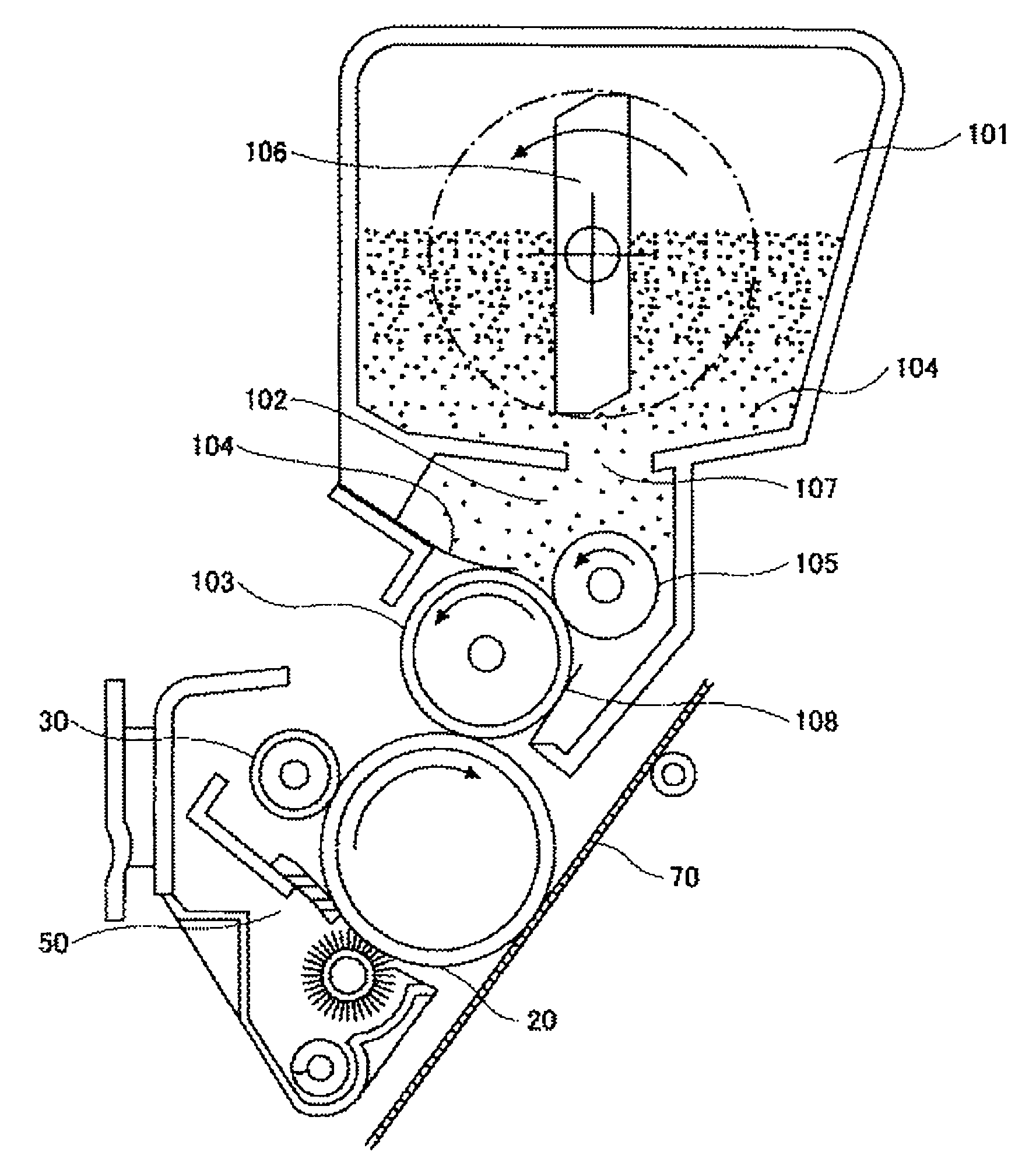
Image

Examples
synthesis example 1
—Preparation of First Binder Resin—
[0120]As vinyl based monomers, 600 g of styrene, 110 g of butyl acrylate, and 30 g of acrylic acid and 30 g of dicumyl peroxide as a polymerization initiator were placed in a dropping funnel. In a 5 liter four-necked flask equipped with a thermometer, a stainless stirrer, a falling type condenser and a nitrogen introducing tube, 1230 g of polyoxypropylene(2.2)-2,2-bis(4-hydroxyphenyl)propane, 290 g of polyoxyethylene(2.2)-2,2-bis(4-hydroxyphenyl)propane as polyols among monomers of polyester, 250 g of isododecenyl succinic acid anhydrate, 310 g of terephthalic acid, 180 g of 1,2,4-benzene tricarboxylic acid anhydrate, and 7 g of dibutyl tin oxide as an esterification catalyst were placed, and subsequently, under a nitrogen atmosphere in a mantle heater, with stirring at a temperature of 160° C., the mixture of the vinyl-based monomer resin and the polymerization initiator was dripped from the above dropping funnel over one hour. Then, with keeping ...
synthesis example 2
—Preparation of Second Binder Resin—
[0121]In a 5 liter four-necked flask equipped with a thermometer, a stainless stirrer, a falling type condenser, and a nitrogen introducing tube, 2210 g of polyoxypropylene(2.2)-2,2-bis(4-hydroxyphenyl)propane as polyol, 850 g of terephthalic acid, 120 g of 1,2,4-benzene tricarboxylic acid anhydrate and 0.5 g of dibutyl tin oxide as an esterification catalyst were placed. Then, under the nitrogen atmosphere in the mantle heater, the temperature was raised to 230° C. and the polycondensation reaction was performed. The polymerization degree was traced using the softening point measured using the constant load extrusion capillary rheometer, and when the desired softening point was reached, the reaction was terminated to obtain a second binder resin. In this way, resin L1 having a softening point (Tm) of 100° C. was synthesized.
production examples 1 to 10
and Comparative Production Examples 1 to 5
—Preparation of Toner—
[0122]A master batch containing 4 parts by mass of C.I. Pigment Red 57:1 relative to 100 parts by mass of the binder resin consisting of the first binder resin and the second binder resin (a mass ratio of the first binder resin to the second binder resin is 50:50; and the types thereof are indicated in Table 1), a paraffin wax at a amount indicated in Table 1, and one part by mass of a boron-based charge controlling agent was sufficiently mixed using a Henschel mixer, and subsequently melt-kneaded using a biaxial extrusion kneader (PCM-30, manufactured by Ikegai Tekkosho). The resulting kneaded product was pressed and extended to a thickness of 2 mm using a cooled press roller, cooled with a cooling belt, and subsequently roughly pulverized using a feather mill. Subsequently, the roughly-pulverized product was pulverized using a mechanical pulverizer (KTM, manufactured by Kawasaki Heavy Industries, Ltd.) to have an aver...
PUM
 Abstract
Description
Claims
Application Information
 - R&D Engineer
- R&D Manager
- IP Professional
- Industry Leading Data Capabilities
- Powerful AI technology
- Patent DNA Extraction
Browse by: Latest US Patents, China's latest patents, Technical Efficacy Thesaurus, Application Domain, Technology Topic.
© 2024 PatSnap. All rights reserved.Legal|Privacy policy|Modern Slavery Act Transparency Statement|Sitemap