
Manufacturing method of photonic crystal

a manufacturing method and technology of photonic crystal, applied in the field of photonic crystal fabrication, can solve the problems of reducing the thickness of the thin film, the inability to act as a specific direction of the photonic crystal, and the complex process to obtain the three-dimensional photonic crystal, etc., to achieve the effect of improving the photonic crystal properties, superior photonic band gap, and high heat resistan

Inactive Publication Date: 2009-07-02
IOWA STATE UNIV RES FOUND +1
View PDF5 Cites 3 Cited by
  • Summary
  • Abstract
  • Description
  • Claims
  • Application Information

AI Technical Summary

Benefits of technology

"The present patent is about a method for manufacturing a photonic crystal with a superior photonic bandgap in three-dimensional directions. The method involves preparing a rod type layer-by-layer structure and then conformally depositing a high-refractive-index material onto it. This method can create a photonic crystal with a complete bandgap for omnidirectional propagation of electromagnetic waves, which can be used in various optical applications. Compared to existing methods, this method has the advantage of being able to create a three-dimensional photonic crystal with a higher refractive index, which enhances the efficiency and functionality of optical devices."

Problems solved by technology

However, since one-dimensional or two-dimensional photonic crystals cannot have a photonic bandgap in a specific direction, they cannot act as a photonic crystal in the specific direction.
This method, however, is basically adapted to fabricate a two-dimensional pattern, and hence a complicated process must be performed to obtain a three-dimensional photonic crystal.
In this case, however, the thickness of a thin film is reduced while the polymer is volatilized during the heat-treatment, leading to the deformation of a thin film.

Method used


Image

  • Manufacturing method of photonic crystal
  • Manufacturing method of photonic crystal
  • Manufacturing method of photonic crystal

Examples


Embodiment Construction

[0023]Hereinafter, specific embodiments will be described in detail with reference to the accompanying drawings. The invention may, however, be embodied in many different forms and should not be construed as being limited to the embodiments set forth herein; rather, these embodiments are provided so that this disclosure will be thorough and complete, and will fully convey the concept of the invention to those skilled in the art.

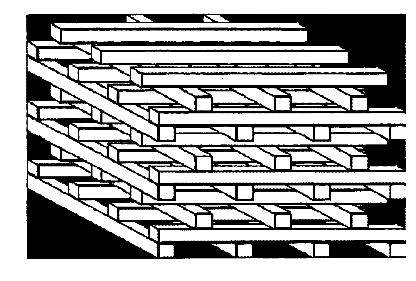
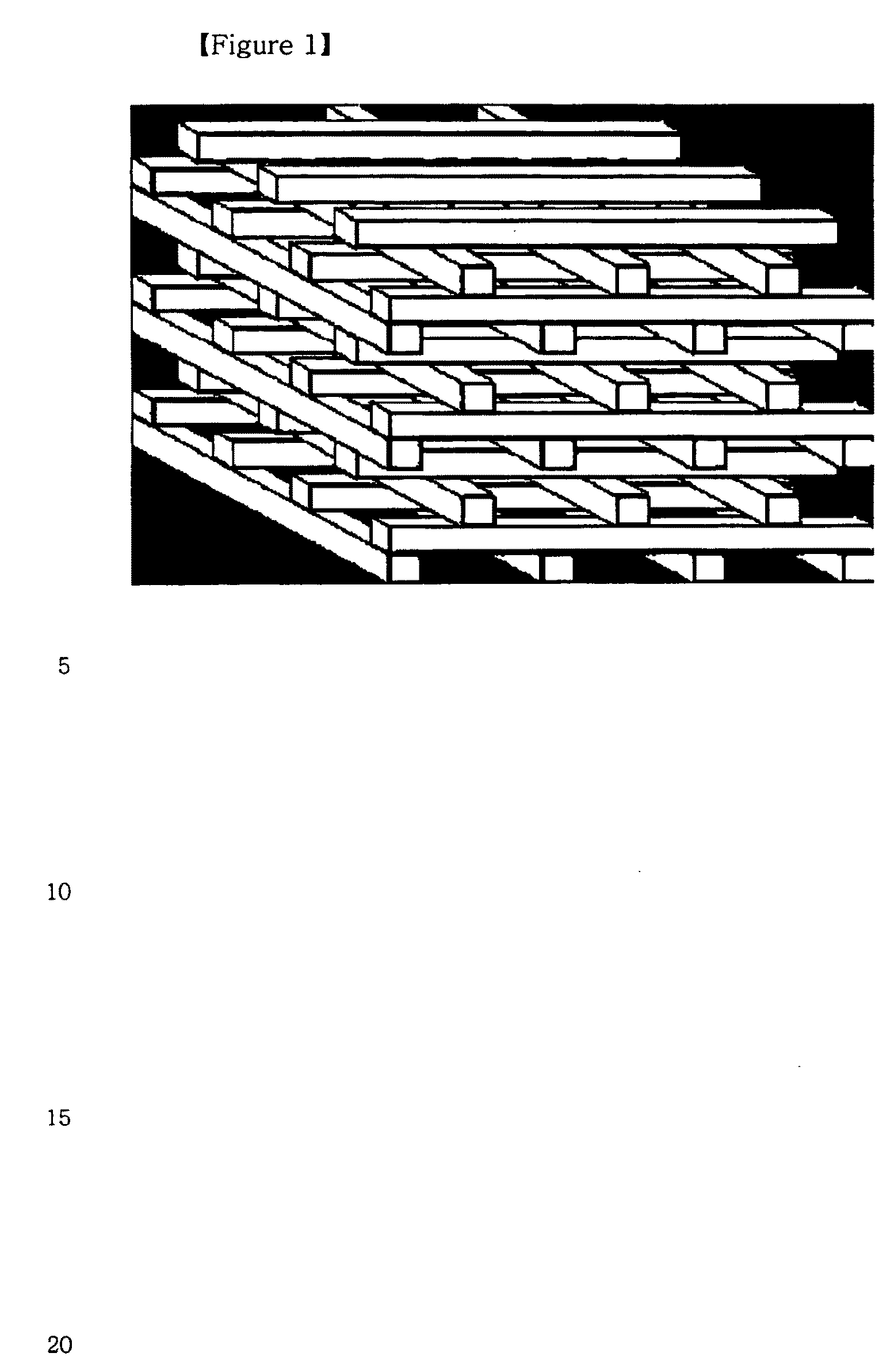
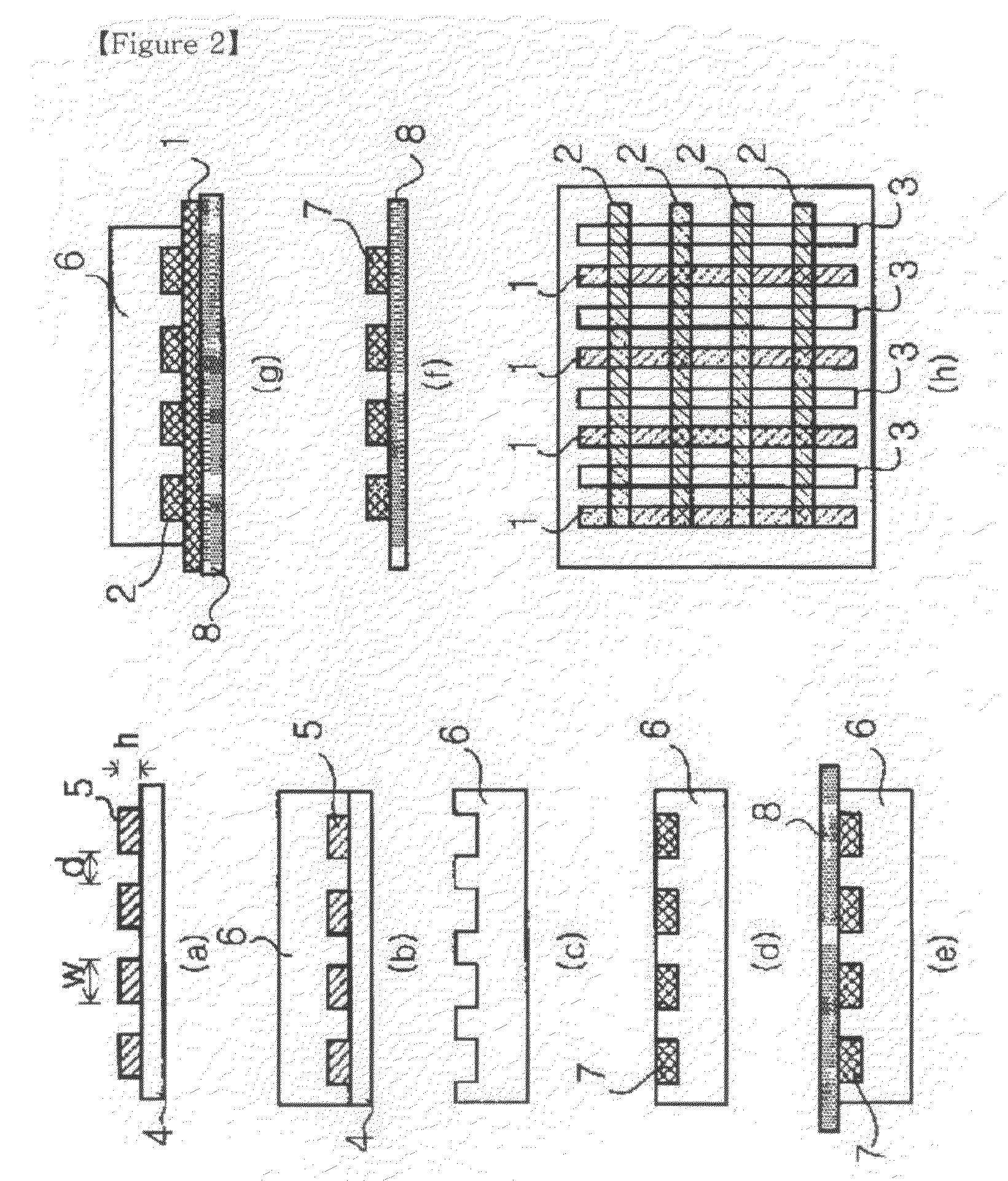
[0024]A photonic crystal structure in accordance with an exemplary embodiment can be formed by preparing a rod type layer-by-layer structure, and a photonic crystal having a superior photonic bandgap can be obtained by conformally depositing a high-refractive-index material on the rod type layer-by-layer structure. The manufacturing method of the rod type layer-by-layer structure may use a microtransfer molding technique, which is disclosed in William R. Childs and Ralph G. Nuzzo, “Decal Transfer Microlithography”, Journal of American Chemical Society, vol. 1...


PUM

PropertyMeasurementUnit
temperatureaaaaaaaaaa
refractive indexaaaaaaaaaa

Abstract

A manufacturing method of a photonic crystal is provided. In the method, a high-refractive-index material is conformally deposited on an exposed portion of a periodic template composed of a low-refractive-index material by an atomic layer deposition process so that a difference in refractive indices or dielectric constants between the template and adjacent air becomes greater, which makes it possible to form a three-dimensional photonic crystal having a superior photonic bandgap. Herein, the three-dimensional structure may be prepared by a layer-by-layer method.

Description

TECHNICAL FIELD[0001]The present disclosure relates to a manufacturing method of a photonic crystal, and more particularly to a manufacturing method of a photonic crystal with a superior photonic bandgap by conformally depositing a high-refractive-index material on a photonic crystal structure.BACKGROUND ART[0002]In general, photonic crystals have a periodic structure in which materials with different refractive indices or dielectric constants are repetitively arranged at regular intervals equivalent to the wavelength of light. Such photonic crystals have a photonic bandgap region in which light in a specific wavelength range are all reflected, and thus the light in the specific wavelength range does not exist inside the photonic crystals.[0003]Particularly, the photonic bandgap of the photonic crystal is determined by a difference in refractive indices of materials or a period of each material. Furthermore, in the case where the photonic crystal has a photonic bandgap in all the di...

Claims


Application Information

Patent Timeline
Patent Type & Authority Applications(United States)
IPC IPC(8): B05D5/06
CPCB82Y20/00G02B6/1225Y10T428/24942B05D5/06G02B6/132
Inventor PARK, IN SUNGLEE, TAE HOAHN, JIN HO
Owner IOWA STATE UNIV RES FOUND
Learn More