Method of minimizing electric power consumption in non-beacon network

a non-beacon network and network technology, applied in power management, high-level techniques, instruments, etc., can solve the problems of increasing the cost necessary to construct a system which uses a main electric power, the inability to use electric power supplied from a battery, so as to minimize the electric power consumption and minimize the effect of electric power consumption

Inactive Publication Date: 2009-07-02
D&S TECH CO LTD +1
View PDF1 Cites 2 Cited by
  • Summary
  • Abstract
  • Description
  • Claims
  • Application Information

AI Technical Summary

Benefits of technology

[0015]Accordingly, the present invention has been made maintaining in mind the above problems occurring in the prior art, and an object of the present invention is to provide a method of constituting an efficient and stable non-beacon network using a small amount of electric power, and, in particular, to provide a method of minimizing electric power consumption in a non-beacon network, in which an FDD, which constitutes a network, does not always maintain an active state but maintains an active state for a predetermined time in each predetermined cycle, thereby minimizing the electric power consumed by the FFD.

Problems solved by technology

However, the FFD does not know when the RFD, which will communicate with the FFD, attempts to communicate, so that the FFD must maintain an active state.
In order to always maintain an active state, as described above, a large amount of electric power should be consumed, so that electric power, supplied from a battery, cannot be used.
Therefore, the parent node must always maintain an active state, so that a large amount of electric power should be consumed, with the result that electric power supplied from a battery cannot be used.
Accordingly, there are problems in that application fields to which a system using a non-beacon network is applied are limited and the cost necessary to construct a system which uses a main electric power is increased.

Method used


Image

  • Method of minimizing electric power consumption in non-beacon network
  • Method of minimizing electric power consumption in non-beacon network
  • Method of minimizing electric power consumption in non-beacon network

Examples


Embodiment Construction

[0023]In order to sufficiently understand advantages of the present invention and the operation of the present invention and objects accomplished through the embodiments of the present invention, the accompanying drawings which illustrate the preferred embodiments of the present invention and details described in the accompanying drawings should be referred to.

[0024]Hereinafter, the present invention will be described in detail by describing preferred embodiments of the present invention with reference to the attached drawings. The same reference numerals, which are used throughout the different drawings, designate the same or similar components.

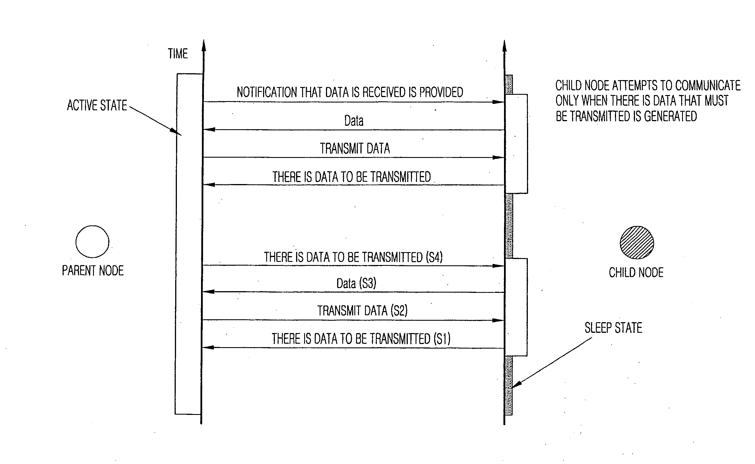
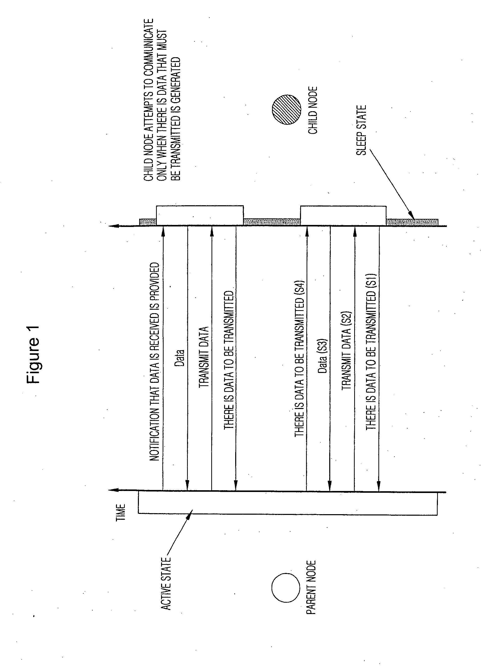
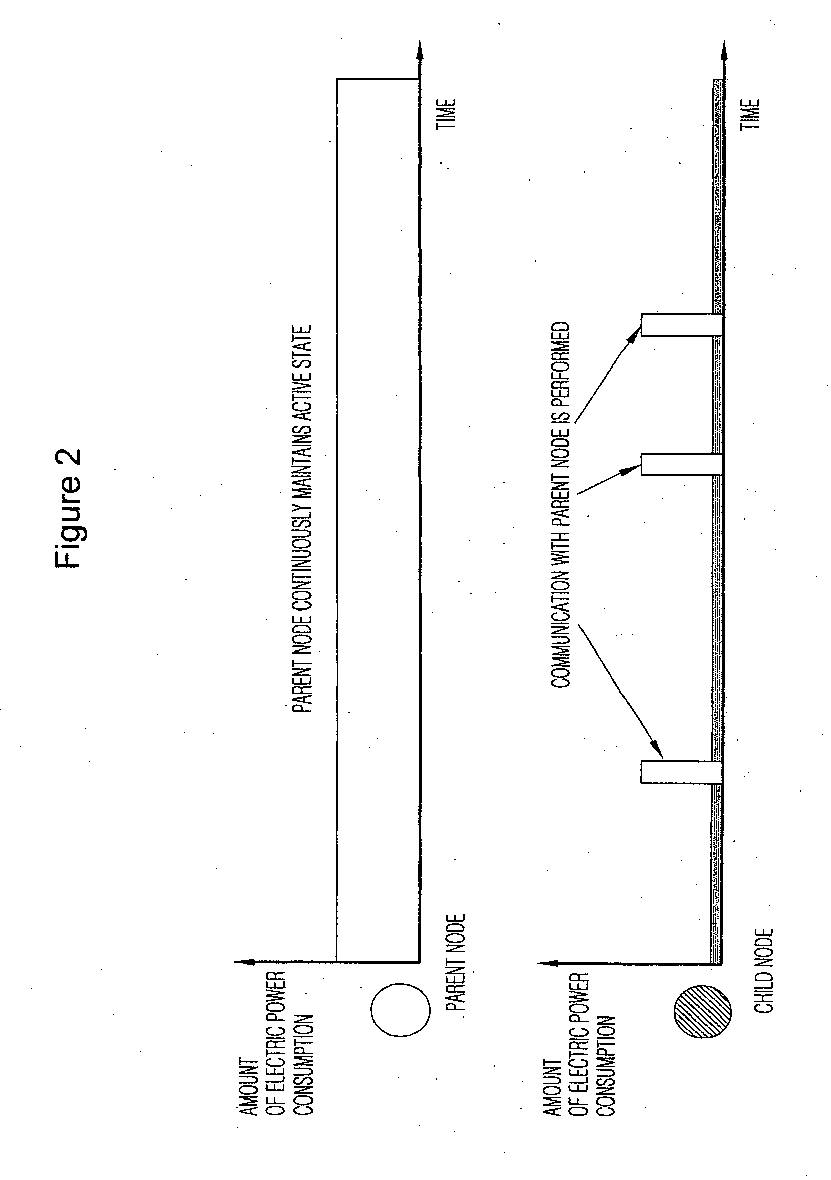
[0025]FIG. 3 is a view showing a communication method using a non-beacon network according to the present invention, and FIG. 4 is a view showing the amount of electric power consumption in a parent node and a child node when the communication method using a non-beacon network according to the present invention is performed.

[0026]Referring t...


PUM


Abstract

Disclosed herein is a method of minimizing electric power consumption in a non-beacon network including a parent node which maintains an active state only for a specific period in each predetermined cycle, and a child node which attempts to communicate for periods only when data is generated. When data that must be transmitted to the child node exists, the child node notifies the parent node that there is data to be transmitted. The child node periodically transmits the same message to the parent node until the parent node maintains an initial active state. If the parent node is switched into an active state and receives the data transmission notification message, the parent node commands the child node to transmit data. The child node transmits the data to the parent node. Thereafter, the parent node notifies the child node that the reception of data is normally performed.

Description

BACKGROUND OF THE INVENTION[0001]1. Field of the Invention[0002]The present invention relates generally to a method of constituting an efficient and stable non-beacon network using a small amount of electric power, and, more particularly, to a method of minimizing electric power consumption in a non-beacon network, in which a Full Function Device (FDD), which constitutes a network, does not always maintain an active state but maintains an active state for a predetermined time in each predetermined cycle, thereby minimizing the electric power consumed by the FFD.[0003]2. Description of the Related Art[0004]Generally, a non-beacon network includes two types of nodes. One type of them is a Reduced Function Device (RFD) which mainly performs a function as a sensor and the other type is an FFD which performs a function as a path for communication data. In the non-beacon network, several tens or several hundreds of RFDs are connected to a single FFD so as to constitute a single network. I...

Claims


Application Information

Patent Timeline
Patent Type & Authority Applications(United States)
IPC IPC(8): G06F1/26
CPCG06F1/3209Y02B60/50H04W84/18H04W52/0216Y02D30/70H04W68/00
Inventor KANG, TAE-JOONJUN, CHAN-HEE
Owner D&S TECH CO LTD
Why Eureka
Try Eureka