
Portable IR Thermometer Having Graphical User Display and Interface

a graphical user and interface technology, applied in the field of portable ir thermometers, can solve problems such as difficulty in implementing complex functions

Active Publication Date: 2009-07-02
JOHN FLUKE MFG CO INC
View PDF12 Cites 72 Cited by
  • Summary
  • Abstract
  • Description
  • Claims
  • Application Information

AI Technical Summary

Benefits of technology

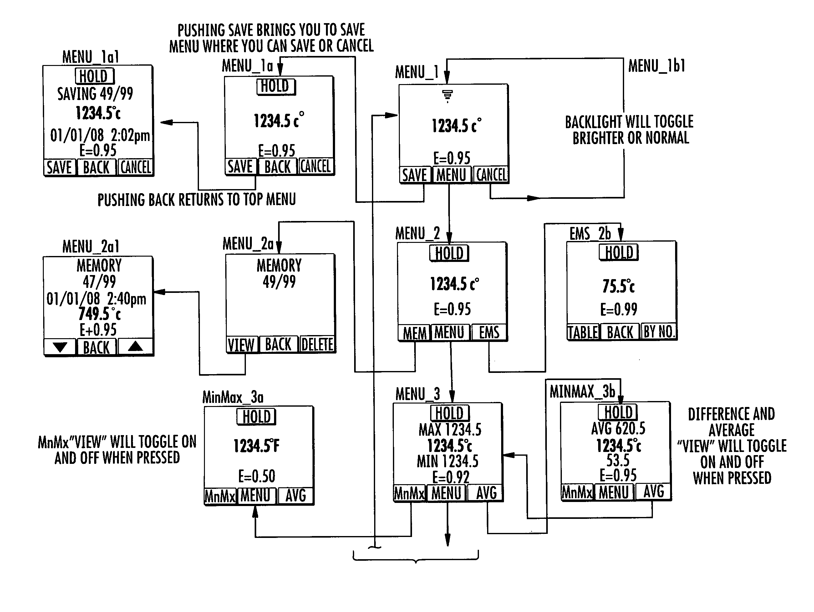
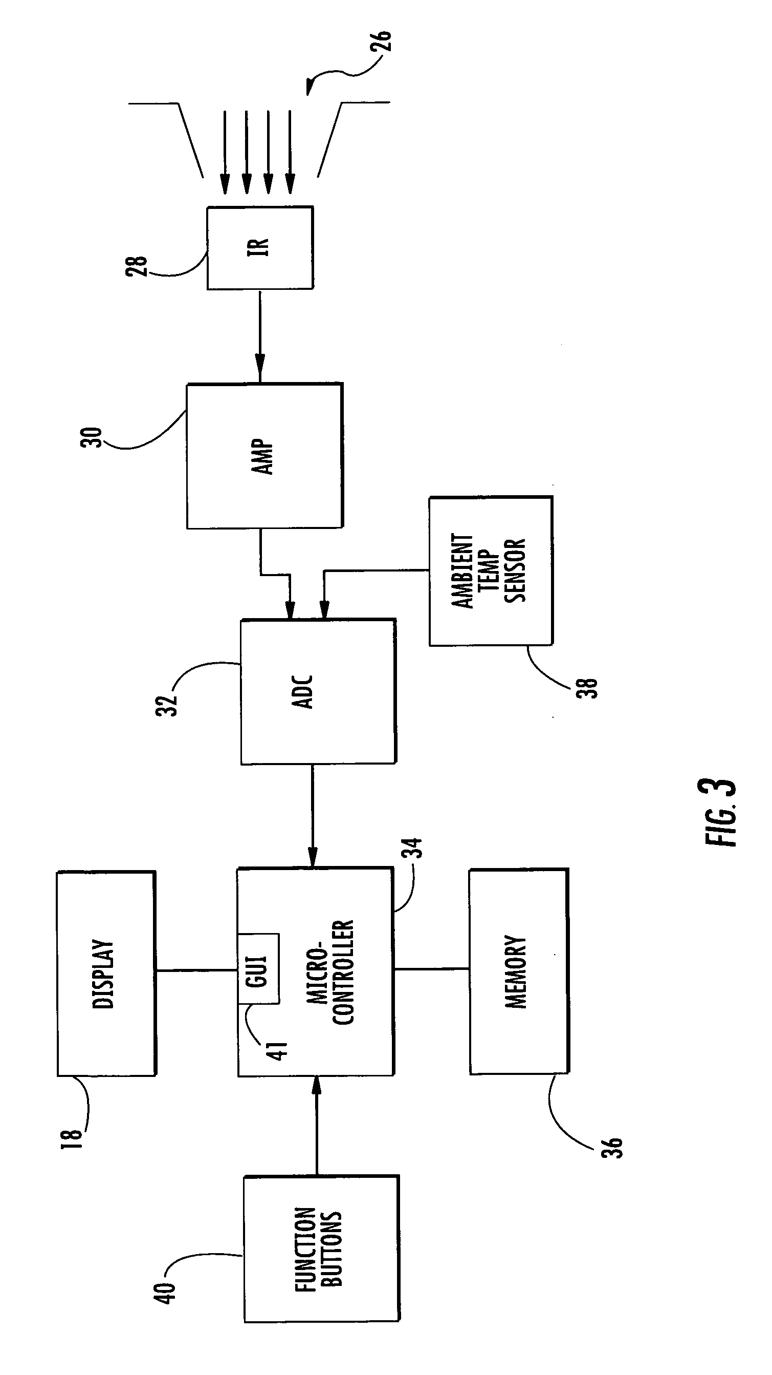
[0004]According to one aspect, the present invention provides a portable noncontact thermometer comprising a hand-held housing defining an aperture for ingress of incident thermal energy from a target location. A thermometer module including a noncontact thermal energy detector is also provided. The thermometer module further includes a microcontroller operative to interpret electrical signals derived from an output of the noncontact thermal energy detector so as to determine temperature at the target location. A graphical display device, such as an LCD dot matrix display device, is fixed with respect to the housing. The display device is capable of providing a graphical user interface having multiple screens variously showing numbers, text and functional icons. The thermometer also includes circuitry, which may comprise the microcontroller itself, in electrical communication with the graphical display device so as to produce the graphical user interface. The functional icons may include icons indicating laser pointer activation and noncontact temperature measurement in progress.

Problems solved by technology

This creates some difficulty to implement complex functions because it necessitates multiple control panel buttons and / or a complicated user interface.

Method used


Image

  • Portable IR Thermometer Having Graphical User Display and Interface
  • Portable IR Thermometer Having Graphical User Display and Interface
  • Portable IR Thermometer Having Graphical User Display and Interface

Examples


Embodiment Construction

[0016]It is to be understood by one of ordinary skill in the art that the present discussion is a description of exemplary embodiments only, and is not intended as limiting the broader aspects of the present invention, which broader aspects are embodied in the exemplary constructions.

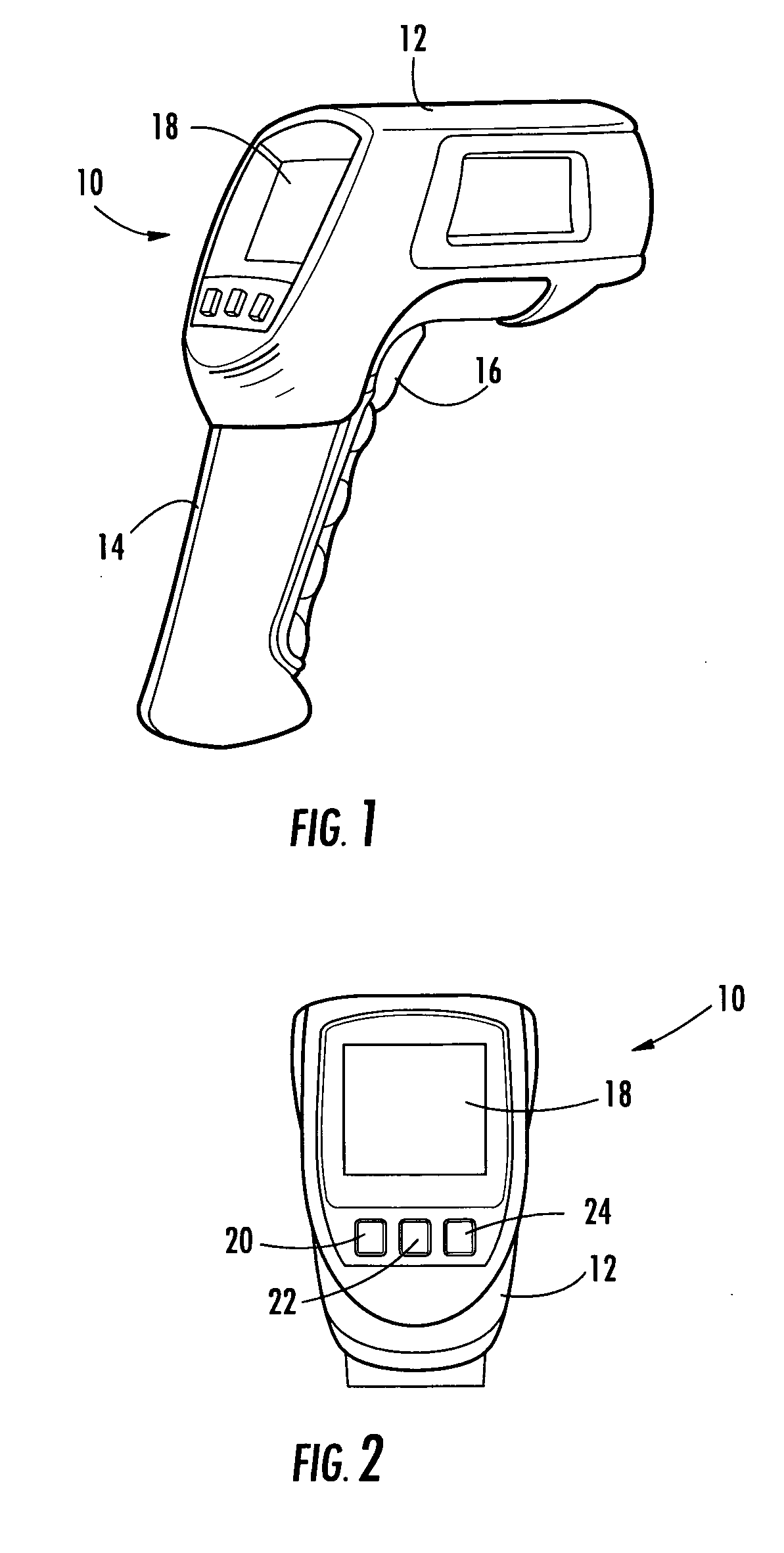
[0017]FIGS. 1 and 2 illustrate an exemplary hand-held thermometer 10 in accordance with principles of the present invention. Thermometer 10 includes an internal detector which collects energy radiated from a selected target. The energy, typically in the form of infrared (IR) radiation, is isolated and focused on the detector. The detector converts the energy into an electrical signal which is then internally processed to yield a temperature value.

[0018]As shown, thermometer 10 includes a housing 12 in which various internal components are located. While any suitable material can be utilized, housing 12 is preferably formed of a rigid high impact plastic material. As shown, housing 12 includes a handle 1...


PUM


Abstract

A portable noncontact thermometer comprising a hand-held housing defining an aperture for ingress of incident thermal energy from a target location. A thermometer module includes a noncontact thermal energy detector impinged by the incident thermal energy. The thermometer module further includes a microcontroller operative to interpret electrical signals derived from an output of the noncontact thermal energy detector so as to determine temperature at the target location. A graphical display device, such as an LCD dot matrix display device, is fixed with respect to the housing. The display device is capable of providing a graphical user interface having multiple screens variously showing numbers, text and functional icons. Preferably, the screens will display function tabs located adjacent to corresponding buttons on the housing. The tabs will change depending on the varying function that may be implemented by pressing a respective button. The thermometer also includes circuitry, which include the microcontroller, in electrical communication with the graphical display device so as to produce the graphical user interface.

Description

BACKGROUND OF THE INVENTION [0001]The present invention relates generally to portable IR thermometers. More particularly, the invention relates to a portable IR thermometer having a graphical user display and interface.[0002]Portable infrared (IR) thermometers allow a user to ascertain the temperature of a remote target using a point and click technique. These instruments are commonly utilized for purposes ranging from automotive diagnostics to food safety. Single point IR thermometers with digital displays have historically been implemented using a fixed-segment LCD or LED display. This creates some difficulty to implement complex functions because it necessitates multiple control panel buttons and / or a complicated user interface.[0003]Various details regarding the construction and operation of noncontact thermometers may be discerned from U.S. Pat. Nos. 4,634,294, 5,640,015 and 6,234,669, each of which is incorporated herein by reference in its entirety.SUMMARY OF THE INVENTION [0...

Claims


Application Information

Patent Timeline
Patent Type & Authority Applications(United States)
IPC IPC(8): G06F3/048G01J5/02
CPCG01J5/02G01J5/025G06F3/0482G01J5/0265G01J5/028G01J5/026
Inventor POMPER, KENNETH A.
Owner JOHN FLUKE MFG CO INC
Learn More